-7-
CPU Port Functions
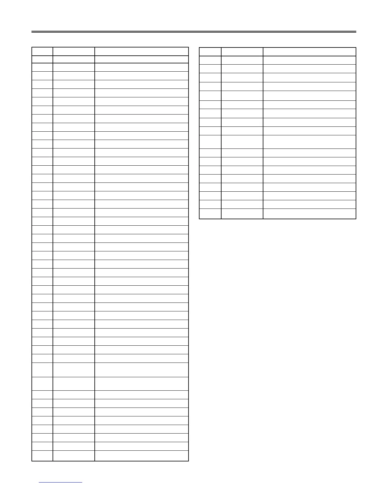
Pin No. Function Name Function
1 SIFout SIF Output (NICAM)
2 IFAGC-F IF AGC Filter
3 SIF-IN SIF Input
4 FM-F Filter for the DC loop of FM detector
5 FMout FM detector output
6 Aud out Audio output
7 SND-APC-F Snd VCO frequency is locked at 500kHz from SIF
8 IF-Vcc DC Supply pin for IF circuit
9 VM/Ext-A-IN External audio signal input
10 ABL Auto Beam Limiter function
11 RGB Vcc Vcc input pin of RGB output block function
12 R-Out R signal output pin function
13 G-Out G signal output pin function
14 B-Out B signal output pin function
15 NC Not Connected
16 Vramp To generate a ramp waveform for the reference V-out
17 V-out Output pin of vertical synchronization ramp signal
18 Iref Producing reference current function
19 H-Vcc Vcc of Horizontal deflection and BUS interface
20 AFC-F AFC Filter pin of horizontal VCO function
21 H-out Horizontal output pin
22 VCD-GND Video Chroma Deflection GND
23 Power Fail IN Power Fail Input function
24 S-TERM IN S-Video input
25 STATUS IN Factory PC mode status (L=ON)
26 Remote IN Remote Control signal receiver
27 P14/PWM1
28 P15/PWM2
29 ON-TIMER LED OUT On timer led out function
30 MUTE OUT Mute out function
31 IIC SDA1 IIC-Bus Data Line
32 IIC SCK1 IIC-Bus Clock Line
33 X’tal Crystal Oscillator
34 X’tal Crystal Oscillator
35 5V Supply (5V)
36 Power Out Power On/Off signal output
37 Bass Expander Bass Expander On/Off function
ON/OFF OUT
38 VIF M OUT VIF M Out/Bilingual Out function
/Bilingual Out
39 AD KEY IN Key signal input
40 RESET RESET pin function
41 FILT FILT pin function
42 GND Ground
43 CCD-Vcc Vcc (5V) pin for 1H delay-line
44 FBP-IN Fly Back Pulse Input
45 YC-C Y/C-C Input function
46 YC-Y Y/C-Y Input function
Pin No. Function Name Function
47 C-APC2 AFC filter pin of chroma VCO. (3.58MHz)
48 DVD-Y DVD-Y Input
49 CB-IN C
B
Input (for DVD)
50 X’tal 4.43MHz Crystal
51 CR-IN C
R
Input (for DVD)
52 SVO/FSC Selected Video Output or FSC Output
53 C-APC-F Chroma APC Filter
54 Ext-Video-IN Ext Video Input & Y Input in S-VHS mode
55 VCD-Vcc Video Chroma Deflection VCC
56 Int-Video-IN Int. Video Input & Chroma Signal Input in S-
VHS mode
57 Blk-F Black peak level detection in black stretch circuit.
58 PIF-APC-F APC filter pin for PLL circuit function.
59 AFT Automatic Fine Tuning Output pin
60 Video out Video Output pin
61 RF AGC RF AGC Output pin
62 IF-GND Ground of IF circuit
63 VIF IN PIF input pin
64 VIF IN PIF input pin
 Loading...