-11-
Service Adjustments with Replacing Memory IC(IC802)
[2] Required Service Adjustments
Readjust the following service adjustments.
Adjustments Service Mode No. & Item
Horizontal centre adjustment Item 01, H-P
Vertical centre adjustment Item 02, V-P
Vertical size adjustment Item 03, V-S
OSD position adjustment Item 04, OSD
RF AGC adjustment Item 05, AGC
AFT adjustment Item 06, VCO
SIF adjustment Item 07, SIF
Grey scale adjustment Item 18-24, DRV
Further adjustment please refer to page 13 and 14.
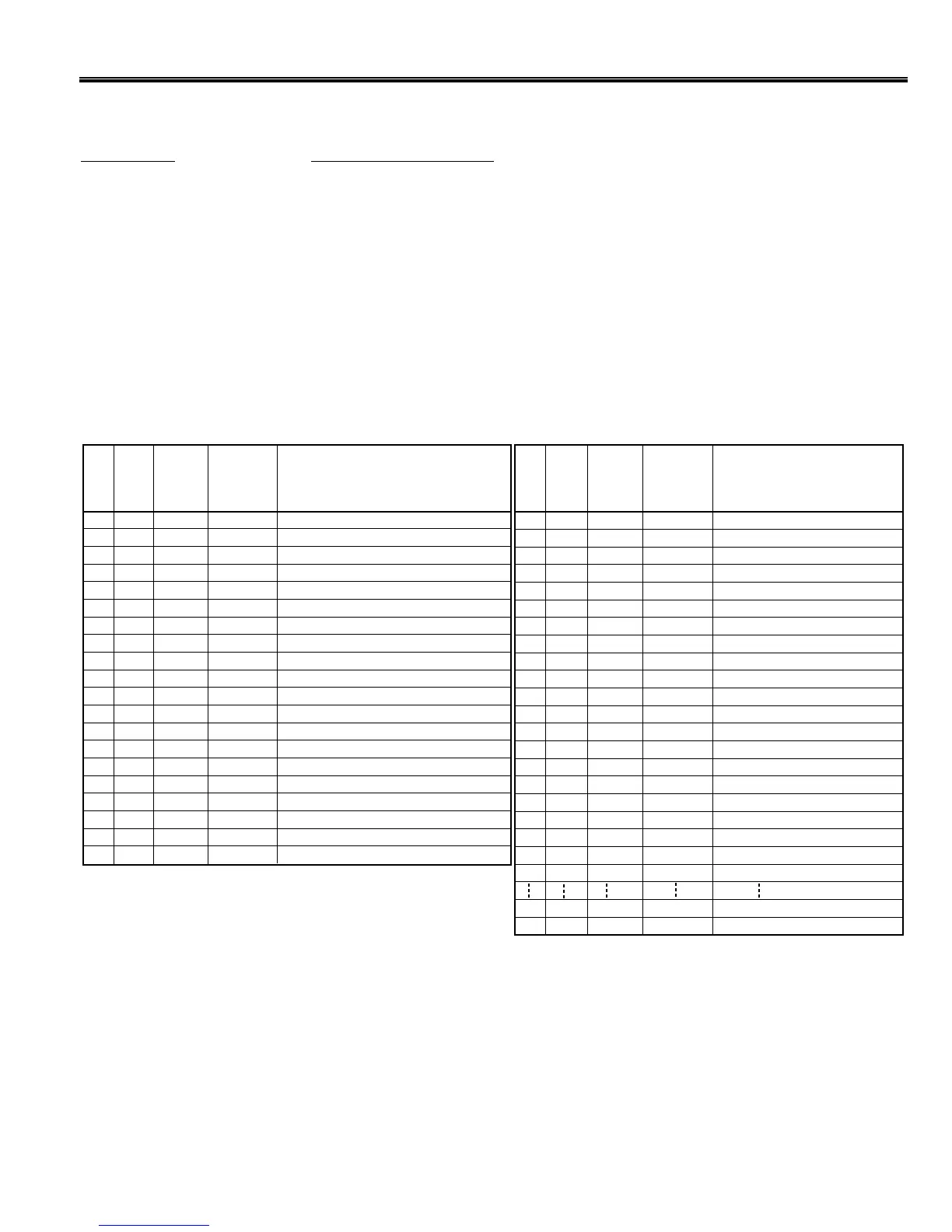
Following table shows the initial values which have been stored in the CPU ROM, and items for the service
adjustments.
Notes:
+ The initial value that the CPU writes down the CPU ROM data to the memory when replaced the memory IC. TV set
may not operate correctly with this initial value. It is required to set up the fine adjustment for service adjustments
described in the above.
Service mode adjustments table in CPU ROM
NO.
ITEM
INITIAL
VALUE
RANGE
OF DATA
FUNCTION
NO.
ITEM
INITIAL
VALUE
RANGE
OF DATA FUNCTION
01
02
03
04
05
06
07
08
09
10
11
12
13
14
15
16
17
18
19
20
H-Phase (H-Centering) AdjustmentH-P
08
00-15
V-Position (V-Centering) AdjustmentV-P
02
00-07
V-Size AdjustmentV-S
70
00-127
OSD H-Position AdjustmentOSD
01
00-15
RF AGC Adjustment
AGC
64
00-127
VCO (AFT) Adjustment
VCO 128
00-255
SIF VCO AdjustmentSIF
00
00-03
Self Adjustment Mode Setting
SELF
00
00-15
DL Time Adjustment
DLT
02
00-03
DL Fine AdjustmentDL F
01
00, 01
Black Stretch On/Off SettingB-ST
00
00, 01
ABCLABCL
01
00, 01
ABCL GainAB-G
00
0, 01
Trap Frequency AdjustmentTRAP
03
00-03
White Back SettingWBK
00
00, 01
Blue Back SettingBBK
00
00, 01
AFC Gain AdjustmentAFCG
02
00-02
Red Bias AdjustmentRBI
00
00-255
Green Bias AdjustmentGBI
00
00-255
Blue Bias AdjustmentBBI
00
00-255
21
22
23
24
25
26
27
28
29
30
31
32
33
34
35
36
37
38
39
40
100
171
172
Red Drive Adjustment
RD
64
00-127
Blue Drive Adjustment
BD
64
00-127
Drive Adjustment
DRV
-
-
Screen Adjustment
1 LINE
-
-
Y/C Separation
Y/C
01
00,01
AV mode contrast under the no signal condition
VCON 10
00-63
VBRI 20
00-63
DVD Colour Adjustment
DCOL
115
00-255
DVD Tint Offset
DTIN
05
-32 - +32
DVD PAL Colour differential value
DPLC
18
-127 - +127
DVD PAL Tint differential value
DPLT
15
-63 - +63
Manufacturing process flag for DVD
DVD-F
00
00-01
1-HDL through flag
HDL-F
00
00-01
MAT switching flag
MAT-F
00
00-01
NICAM/A2 carrier setting
NICAM
00
00-01
DVD 1 chip colour adjustment
COFF
00
00-03
BBE MID level adjustment
BBE-M
128
00-255
BBE HIGH level adjustment
BBE-H
00
00-255
Y/C IC emphasis setting
ENH 00
00-01
Option setting
CPU Debug Data
CPU Debug Data
Check Code
OPT
R00
R71
R72
255
FF
FF
FF
00-255
00-FFh
00-FFh
00-FFh
AV mode brightness under the no signal condition
 Loading...