(1) Receive the monochrome circular pattern.
(2) Set the brightness and contrast to normal.
(3) Select [H-P] in the service mode.
(4) Change value to be optimum horizontal centre position.
(5) Exit from the service mode.
Item 01 [H-P] HORIZONTAL CENTRE
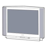
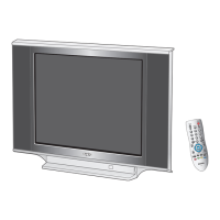
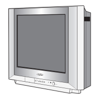
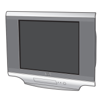
Service Mode Adjustments
Horizontal centre
Following adjustments should be carried out when the memory IC is replaced. How to enter the service mode and
adjust values, please refer to “ Entering to Service mode” on page 12.
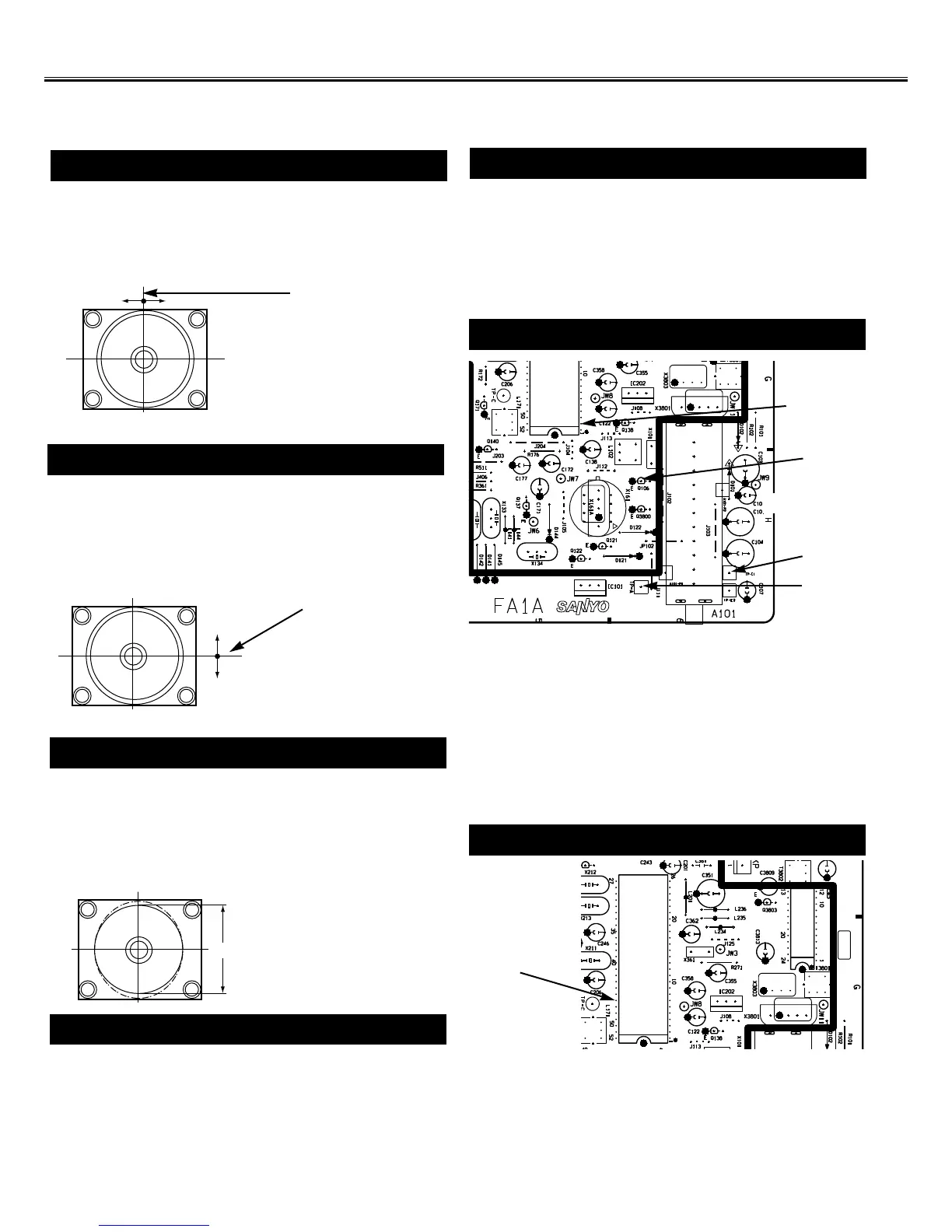
MAIN BOARD
IC201 pin-2
Q106
Pin-2
IC201
pin-46
MAIN BOARD
TP-A
(1) Receive the monochrome circular pattern.
(2) Set the brightness and contrast to maximum.
(3) Select [V-P] in the service mode.
(4) Change value to be optimum vertical centre position.
(5) Exit from the service mode.
Item 02 [V-P] VERTICAL CENTRE
Vertical centre
(1) Receive the monochrome circular pattern.
(2) Set the brightness and contrast to maximum.
(3) Select [V-S] in the service mode.
(4) Change value to be optimum vertical size.
(5) Exit from the service mode.
(1) Receive the monochrome circular pattern.
(2) Set the brightness and contrast to normal.
(3) Select [OSD] in the service mode.
(4) Change value to be proper OSD position.
(5) Exit from the service mode.
Item 04 [OSD] OSD POSITION
Item 03 [V-S] VERTICAL SIZE
Vertical size
NOTE: Do not attempt this adjustment with weak signal.
(1) Tune the receiver to most clearest (or strongest) VHF
station in your area. Set the brightness and contrast
controls to maximum. Set the colour control to mini-
mum.
(2) Select [AGC] in the service mode.
(3) Change value until the snow noise just disappears.
Item 05 [AGC] AGC
Item 06 [VCO] AFT
(1) Input the SG signal to collector of Q106.
SG signal frequency : 38.0MHz
SG signal level : 70 dB~75dB
SG signal : COLOUR bar
(2) Connect a short clip between the base of Q106 and
ground. Connect a short clip between TP-A and TP-E.
(3) Connect oscilloscope to pin 2 of IC201.
(4) Select [VCO] in the service mode.
(5) Change value until the voltage to be 4.5 ± 1.0V.
(6) Exit from the service mode.
Item 07 [SIF] SIF
(1) Tune the receiver to the clearest station with System
B/G(5.5MHz) in your area.
(2) Connect DC voltmeter to pin 46 of IC201 and ground.
(3) Select [SIF] in the service mode.
(4) Change value until the voltage to be about 3.0V.
(5) Exit from the service mode.
TP-E
 Loading...