– 6 –
MECHANICAL DISASSEMBLY
CAUTION: This LCD TV uses several different kinds of screws. Using the correct screw is necessary to
prevent damage. Lead wires must be redressed to their previous locations after servicing.
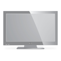
STAND REMOVAL
Position TV face down on a padded or cushioned surface
to protect the screen and finish.
Remove 4 screws (B: 6X16) to take the stand off.
BACK CABINET REMOVAL
1. Remove the screws shown in figure.
(C:3x14, 12 pcs.; D4x8, 4 pcs.; A3x6, 1 pcs.)
2. Lift the back cabinet and remove the lead wire connector.
3. Take the back cabinet off.
[ATTENTION]
Please do not tighten the (D) screw too strongly when you
install the back cabinet againg. The screw comes not to be
tightened.
MAIN BOARD REMOVAL
Remove 7 screws (C:3x6) to take the main board off.
POWER UNIT REMOVAL
Remove 7 screws (C:3x6) to take the power unit off.
 Loading...