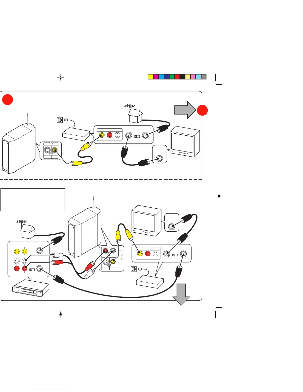
Hook up (Using RF Modulator, not supplied)
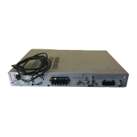
Sub-woofer, TV and RF Modulator connections
Sub-woofer, VCR, TV and RF Modulator connections
Set the channel number CH3 (or CH4) on all TV, VCR
and RF Modulator, whichever is not used for regular
broadcasts in your area.
TV
Set the channel number CH3 (or CH4) on both TV and RF Modula-
tor, whichever is not used for regular broadcasts in your area.
TV
RF Modulator
RF Modulator
HiFi Stereo VCR
TV/CATV
Antenna Cable
TV/CATV
Antenna Cable
To AC 120V, 60Hz
To AC 120V, 60Hz
5A
Important Information:
Do not connect the unit to a VCR directly.
The playback picture will be distorted
because DVD video discs are copy
protected.
If your TV has a Video
input jack...
5
Yes
No
6A
After all connec-
tions have been
made, connect
the power cord
of sub-woofer
and rear speaker
to a 120V AC
60Hz outlet.
To AC 120V,
60Hz
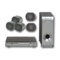
Sub-woofer (Powered speaker)
Sub-woofer
(Powered
speaker)
DWM-4500 Quick(Eng).p65 05.1.12, 1:15 PM3
 Loading...