Do you have a question about the Sanyo EM-G4753 and is the answer not in the manual?
Essential safety measures for microwave oven servicing, covering operation, checks, and protective practices.
Explains complete circuit diagrams for diagnosing operational and fault conditions.
Detailed steps for safely removing and reinstalling the magnetron.
Procedures for testing, replacing, and adjusting door safety interlock switches.
Methods for identifying the root causes of microwave oven malfunctions through inspection.
How to measure and test for microwave radiation leakage from the oven.
Methods to fix excessive microwave radiation leakage from the oven.
Essential safety tasks before performing maintenance on critical components.
Detailed guide for testing, replacing, and adjusting safety interlock switches.
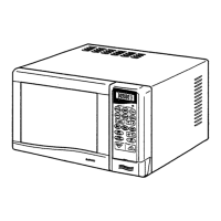
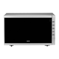
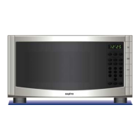
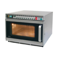
This document is a service manual for Sanyo Microwave Ovens, covering models EM-S1053, EM-G2053, EM-S1063, EM-G2063, EM-S1553, EM-G2553, EM-S1563, EM-G2563, EM-S3553, and EM-G4753. It provides comprehensive information on the structure, working principles, assembly, disassembly, breakdown analysis, and repair methods for these microwave ovens.
A microwave oven is an appliance that heats food using microwave energy. The core function involves converting electrical energy into microwave energy, which then interacts with food molecules to generate heat. This process relies on the principles of dielectric loss of polar molecules and conductive loss of ions within the food when exposed to a high-frequency electromagnetic field. The oven is designed to contain and direct these microwaves efficiently to ensure even and effective heating.
Heating Principle: Microwave heating is based on the interaction of food with a microwave field. The power absorbed by a unit volume of matter (Pa) is given by the formula: Pa = KE fErtgo, where K is a constant, E is the microwave frequency, f is the microwave frequency, tgo is the loss angle tangent of the heated matter, and Er is the relative dielectric constant of the heated matter.
High Voltage Rectifying Circuit: The ovens utilize a single-phase, semi-wave, double voltage rectifying circuit. This circuit typically includes a high voltage capacitor, a high voltage diode, and a magnetic leakage transformer. It boosts the 230V power frequency voltage to approximately 4000V DC, which is then supplied to the magnetron.
Microwave Generator: The heart of the microwave oven is the magnetron, which converts the direct high voltage into microwave energy. The manual specifies the use of continuous wave magnetrons. The anode voltage-current characteristic shows that the magnetron starts oscillating and its current increases significantly once the anode voltage reaches a "THRESHOLD" value. A steady direct current voltage is crucial for stable output.
Cooling System: To prevent overheating and ensure the longevity of the magnetron, a compelling wind cooling system is employed. This system includes a fan motor, air duct, air entrance, and air vent. The cooling wind is directed parallel to the magnetron's cooling fins. The fan's blast amount must meet specific requirements to avoid damage to the magnetron.
Electric Control System:
Door Interlock Switch: This safety mechanism ensures the oven does not operate with the door open. It comprises latch switches (S1, S2) and a pilot switch (S3). When the door is closed, S1 and S2 are closed, and S3 is open, allowing the oven to prepare for operation. If the door is opened during operation, S1 and S2 open, S3 closes, immediately stopping microwave generation and preventing short-circuits.
Time and Power Distributor: This system, found in mechanical control ovens, uses a timer motor and gear switches (S4, S5). S4 controls the heating duration, while S5 regulates microwave output, often through "CONDUCTION RATIO CONTROL" by varying the magnetron's working time within a cycle. For example, in a WP700 model, S5 works in 30-second cycles, with adjustable conduct times for different power levels (e.g., 14.4 seconds for defrost at 336W, continuous for "HIGH" at 700W).
Thermal Cutout: A thermal sensor switch, usually located on the magnetron's shell and series-connected to its primary circuit, controls power input. It automatically cuts off power to the magnetron if its temperature exceeds a safe limit due to cooling system malfunction, preventing damage. It has a self-resuming character, closing again once the temperature drops.
Heating Chamber: This is where food is heated. The manual describes it as a typical carton-type heating chamber, functioning as a microwave resonant cavity. It includes an oven door, oven cavity, wave guide, and coupling appliance. Key components for even heating include a turntable glass tray, roller shaft, and turntable supporter. Safety features include a steel filament or perforated metal plate in the door window for shielding, and a "CURRENT-RESISTANT" seal based on the "TRANSFERING LINE ONE-FOURTHWAVE LENGTH IMPEDANCE CHANGER" theory to prevent microwave leakage.
Safety Standards: Microwave leakage should not exceed 5 milliwatt/cm2 according to IEC STANDARD, and preferably under 1 milliwatt/cm2 after repair. Insulation resistance between electric metal parts and the non-electric metal cabinet should be at least 2 megaohms.
The manual primarily focuses on service and repair, but implicitly highlights several usage features:
The service manual provides detailed instructions for maintenance and repair, emphasizing safety precautions:
| Brand | Sanyo |
|---|---|
| Model | EM-G4753 |
| Category | Microwave Oven |
| Language | English |