EasyManua.ls Logo

Sanyo LCD-32XF7 User Manual

Sanyo LCD-32XF7
50 pages
To Next Page IconTo Next Page
Page #1 background imageLoading...
Page #1 background image
SERVICE MANUAL
LCD Television
N7TV
FILE NO.
Model No. LCD-32XF7
(Argentina)
Give complete “SERVICE REF. NO.” for parts order
or servicing. It is shown on the rating label at the
cabinet back of the unit.
This T.V. receiver will not work properly in for-
eign countries where the television transmis-
sion system and power source differ from the
design specifications. Refer to the specification
table.
Service Ref. No. LCD-32XF7-00
Product Code:113022416
Original Version
Chassis Series: UE6-L
Contents
Safety Notice . . . . . . . . . . . . . . . . . . . . . . . . . . . . . . . . . 2
Specifications . . . . . . . . . . . . . . . . . . . . . . . . . . . . . . . . . 3
Chassis Block Diagrams . . . . . . . . . . . . . . . . . . . . . . . . 4
IC Block Diagrams . . . . . . . . . . . . . . . . . . . . . . . . . . . . . 6
On-screen Service Menu System . . . . . . . . . . . . . . . . 14
Service Adjustments. . . . . . . . . . . . . . . . . . . . . . . . . . . 20
Mechanical Disassembly . . . . . . . . . . . . . . . . . . . . . . 21
Cabinet Parts List. . . . . . . . . . . . . . . . . . . . . . . . . . . . . 25
Chassis Electrical Parts List. . . . . . . . . . . . . . . . . . . . . 27
Printed Wiring Board . . . . . . . . . . . . . . . . . . . . . . . . . . 45
Question and Answer IconNeed help?

Do you have a question about the Sanyo LCD-32XF7 and is the answer not in the manual?

Sanyo LCD-32XF7 Specifications

General IconGeneral
BrandSanyo
ModelLCD-32XF7
CategoryLCD TV
LanguageEnglish

Summary

Safety Notice

Safety Precautions

Essential safety measures for operating and servicing the TV.

Product Safety Notice

Guidelines for component replacement to ensure product safety.

Chassis Block Diagram

Main Signal Processing Circuit

Overview of the main signal processing path within the chassis.

IC Block Diagrams

IC601 QL6599DTR Block Diagram

Block diagram for IC601 (QL6599DTR).

IC750 QPS331TQFP64M Block Diagram

Block diagram for IC750 (QPS331TQFP64M).

IC8001 MST6M16 Block Diagram

Block diagram for the main processing IC (MST6M16).

IC8005 QXXAVC961M Block Diagram

Block diagram for IC8005 (QXXAVC961M).

On-screen Service Menu System

How to Enter Service Menu

Step-by-step guide to access the service menu on the TV.

Service Adjustment Data Table

Table listing initial data for various service adjustments.

Service Adjustments

Setting the Initial Data

Procedure for setting initial adjustment data in the service menu.

White and Black Balance Adjustment

Steps for adjusting white and black balance for picture quality.

Mechanical Disassembly

Stand Removal

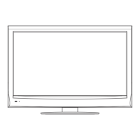
Instructions for removing the TV stand.

Lid Back Removal

Procedure for removing the rear cover of the TV.

Main Board and Terminal Base Removal

Steps to remove the main PWB and terminal base.

Speaker Removal

Instructions for removing the speakers from the TV.

Printed Wiring Board

Main Board Part Side Layout

Component layout diagram for the main board (part side).

Main Board Solder Side Layout

Component layout diagram for the main board (solder side).

Power Board Part Side Layout

Component layout diagram for the power board (part side).