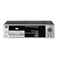
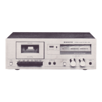
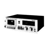
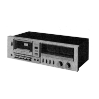
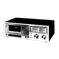
This document is a service manual for the Sanyo RD 250 Stereo Cassette Deck, providing detailed information for its adjustment, maintenance, and repair.
The Sanyo RD 250 is a stereo cassette deck designed for recording and playback of audio on magnetic tape. It supports various tape types including Metal, CrO2 (Chromium Dioxide), and normal tape, offering flexibility for different recording needs. A key feature of this deck is its integrated Dolby Noise Reduction (NR) system, which helps to reduce tape hiss during recording and playback, improving the overall audio quality.
Important Technical Specifications:
- Recording System: AC bias, 4-track stereo. This system uses a high-frequency alternating current to linearize the magnetic recording process, resulting in lower distortion and a wider frequency response.
- Erasing System: AC erasing, 2-track. Similar to the recording bias, AC erasing uses a high-frequency signal to effectively demagnetize the tape, preparing it for new recordings.
- Tape Speed: 4.75 cm/sec. (1-7/8 i.p.s. - inches per second). This is the standard speed for compact cassette decks, balancing tape capacity with audio quality.
- Rewind and Fast Forward Time: Approximately 110 seconds for a C-60 cassette. This indicates a reasonably quick tape transport mechanism for convenience.
- Wow and Flutter: 0.05% (WRMS - Weighted Root Mean Square). This is a critical specification for tape decks, indicating the stability of the tape speed. A low wow and flutter value ensures that playback pitch remains consistent and free from audible fluctuations.
- Frequency Response:
- Metal tape: 40 – 17,000 Hz. Metal tapes offer the widest frequency response due to their superior magnetic properties.
- CrO2 tape: 40 – 16,000 Hz. Chromium Dioxide tapes provide a good balance of frequency response and noise characteristics.
- Normal tape: 40 – 13,000 Hz. Normal (Type I) tapes are the most common and offer a decent frequency range for general use.
- Signal-to-Noise Ratio (metal tape):
- 65 dB (Dolby NR on). The Dolby NR system significantly improves the signal-to-noise ratio by reducing background noise.
- 57 dB (Dolby NR off). Without Dolby NR, the inherent noise of the tape and electronics is more apparent.
- Inputs:
- MIC: 400 ohms to 10 kohms (0.3 mV). This input is suitable for connecting microphones for direct recording.
- LINE IN: 50 kohms (100 mV). This is a standard line-level input for connecting external audio sources like CD players, tuners, or other audio components.
- Outputs:
- LINE OUT: 2 kohms (0.4 V). This output allows the deck to be connected to an amplifier or receiver.
- PHONES: 8 ohms to 10 kohms. A headphone output for private listening.
- Power Requirements: AC: 220 V, 50 Hz. This specifies the electrical power needed for the European market.
- Power Consumption: 12 W. A relatively low power consumption for a cassette deck.
- Dimensions (Approx.): 420 (W) x 220 (D) x 110 (H) mm (16-1/2" x 8-5/8" x 4-3/8"). These are the physical dimensions of the unit.
- Weight (Approx.): 4 kg (9 lbs.). The weight of the cassette deck.
Usage Features:
The Sanyo RD 250 features a user-friendly interface with push-button controls for standard tape transport functions: POWER/EJECT, REC/REW/F.FWD, PLAY/STOP/PAUSE, and DOLBY NR/INPUT/TAPE. Rotary knobs are provided for INPUT LEVEL adjustment, allowing precise control over recording levels. The deck also includes a level meter with an LED indicator for monitoring audio levels, specifically a +3 dB LED to indicate peak levels. Tape selector switches allow the user to choose between Metal, CrO2, and Normal tape types, optimizing the recording and playback equalization for each. A MIC input is available for direct microphone connection, and LINE IN/OUT terminals facilitate integration into a larger audio system. The Dolby NR switch enables or disables the noise reduction system based on user preference or tape type.
Maintenance Features:
The service manual provides comprehensive instructions for various adjustments and maintenance procedures, crucial for ensuring the deck's optimal performance and longevity.
- Mechanism Adjustment: Before any measurements, it is emphasized to clean the head, capstan, and pinch roller, and to check torque and tensions.
- Head Replacement and Azimuth Adjustment: Detailed steps are provided for replacing the head, demagnetizing and cleaning it, and then adjusting the azimuth. This involves playing a test tape (VTT-658, 10 kHz) and turning an azimuth adjusting screw to maximize the left and right outputs for both sides of the cassette.
- Belt Replacement: Instructions are given for replacing the Flat Belt (Flywheel) and Square Belt (Idler), with specific part numbers provided.
- Motor Replacement and Speed Regulation: To adjust the tape speed, a test tape (MTT-111, 3 kHz) is played, and an SVR (variable resistor) on the back of the motor is adjusted with a screwdriver until a frequency counter indicates 3,000 Hz.
- Adjustment of Amplifier Unit: These adjustments are to be performed after cleaning the head and adjusting its azimuth. The input switch should be set to LINE.
- Playback Output Adjustment: Using a Dolby test tape (MTT-150), SVR701 (L-ch) and SVR801 (R-ch) are adjusted until the playback output is 0.55 V.
- Level Meter Adjustment: With the same test tape, SVR703 (L-ch) and SVR803 (R-ch) are adjusted until the +3 dB LED on the level meter lights up.
- Record/Playback Output Adjustment: This involves feeding a -20 dB, 1 kHz metal tape signal, pausing in record mode, adjusting the input level knob for a 0.4 V monitor output, recording, rewinding, playing back, and then adjusting SVR702 (L-ch) and SVR802 (R-ch) if the playback output is not 0.4 V. This process is repeated for precision.
- Record/Playback Frequency Characteristics Adjustment and Checking: This procedure involves setting the input level, attenuating the signal, changing the frequency of the audio signal generator (1 kHz to 10 kHz), recording, rewinding, and playing back. SVR601 (L-ch) and SVR602 (R-ch) are adjusted if the 10 kHz signal playback output is not within ±1 dB of the 1 kHz signal (0 dB reference).
- Parts List and Exploded Views: The manual includes detailed parts lists for the packing, cabinet & chassis, AMP PCB assembly, DOLBY/INPUT/TAPE SWITCH PCB assembly, RECORD LED PCB assembly, PAUSE LED PCB assembly, INPUT LEVEL VOLUME PCB assembly, MIC SOCKET PCB assembly, PHONES PCB assembly, POWER SWITCH PCB assembly, LAMP PCB assembly, LEVEL INDICATOR PCB assembly, and the mechanism itself (TM-250US). Exploded views of the cabinet & chassis and the mechanism are provided to aid in disassembly and reassembly.
- Schematic and Wiring Diagrams: Comprehensive schematic and wiring diagrams are included, essential for troubleshooting and repair of the electronic circuits.
A crucial note in the manual highlights that "The POWER switch is mounted on the secondary side and does not disconnect the set from AC-power, even when switched off." This implies that the unit remains connected to the mains supply even when powered off via the front panel switch, and should be unplugged from the wall socket for complete power disconnection during servicing.
The specifications mentioned are based on the IHF (Institute of High Fidelity) measurements standard, which may differ from DIN (Deutsches Institut für Normung) standards, and thus direct comparisons should be made with caution. The manufacturer also states that specifications are subject to change without notice.