EasyManua.ls Logo

Sanyo RP 8260UM User Manual

Sanyo RP 8260UM
8 pages
To Next Page IconTo Next Page
Page #1 background imageLoading...
Page #1 background image
SERVICE
MANUAL
PORTABLE
RADIO
RP
8260UM
SPECIFICATIONS
Frequency
ranges:
LW
150
285
kHz
Output
power:
MW
525
1605
kHz
SW
5.95
18.0
MHz
Transistor:
FM
87.5
108
MHz
Diode:
Intermediate:
LW/MW/SW
470
kHz
Power
source:
FM
10.7
MHz
Sensitivity:
LW
400unV/m
Current
consumption:
(for
50mW
output)
MW
100uV/m
Speaker:
SW
25uV/m
Dimensions:
FM
3uV
Weight:
Maximam
1300
mW
Undistorted
800
mW
11
16
DC
4.5for1.5V
“UM-1”
Size
x
3
AC
120/220V,
50/60
Hz
No
signal
30mA
92
mm,
8ohm
257mm(W)
x
162mm(H)
x
75mm(D)
Approx.
Approx.
1.5
kg
NOTE:
Specifications
are
subject
to
change
without
notice.
WM-4633
Question and Answer IconNeed help?

Do you have a question about the Sanyo RP 8260UM and is the answer not in the manual?

Sanyo RP 8260UM Specifications

General IconGeneral
BrandSanyo
ModelRP 8260UM
CategoryPortable Radio
TypeAM/FM Radio
Power SourceBattery
Battery TypeD
Battery Quantity2
BandAM/FM
Speaker Size3 inches

Summary

Portable Radio Specifications

Frequency and Sensitivity Ranges

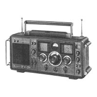
Details radio reception frequency bands and sensitivity levels for LW, MW, SW, and FM.

Power Output and Source

Specifies maximum undistorted output power and available power sources (DC and AC).

Component and Physical Specifications

Lists transistor/diode counts, current consumption, speaker, dimensions, and weight.

Cabinet and Chassis Disassembly

Removing External Components

Instructions for removing the back lid, knobs, and antenna cord from the cabinet.

Separating Chassis and Internal Parts

Steps to detach the chassis, pointer, dial scale, and tuning shaft assembly.

Printed Circuit Board Disassembly

Dial Rope Securing Before PCB Removal

Important note to secure the dial rope with string before PCB disassembly.

Dial Cord Stringing Procedure

Dial Cord and Spring Preparation

Preparing the dial cord and tension spring for stringing.

Cord Routing and Attachment

Detailed steps for routing the dial cord around the drum and tuning shaft.

Meter Adjustment Specifications

Battery Meter Adjustment

Procedure for adjusting the battery meter using specific settings and R330.

Tuning Meter Checking and Adjustment

Steps to check and adjust the tuning meter, including IF Transformer T303.

Alignment Procedures

General Alignment Conditions

Pre-alignment conditions including volume, signal input, meter usage, and modulation standards.

Band-Specific Alignment Procedures

Detailed alignment steps for LW, MW, SW, and FM bands using signal generator and output meter.

Parts Location Diagram

Wiring Diagram

Schematic Diagram

Parts List

Packing and Cabinet Parts

List of packing materials and cabinet/chassis related components.

Electrical and Fixing Parts

List of electrical components, fixing parts, and hardware.

Resistors and Capacitors

Detailed list of resistors and capacitors with their values and specifications.
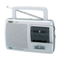
Related product manuals