EasyManua.ls Logo

Sanyo SAP-CMRV3144EH User Manual

Sanyo SAP-CMRV3144EH
114 pages
To Next Page IconTo Next Page
Page #1 background imageLoading...
Page #1 background image
TECHNICAL & SERVICE MANUAL
OUTDOOR UNIT : SAP-CMRV1424EH
SAP-CMRV1924EH
SAP-CMRV1934EH
SAP-CMRV2444EH
SAP-CMRV3144EH
SAP-CMRV1424EH
SAP-CMRV1924EH
SAP-CMRV1934EH
SAP-CMRV2444EH
SAP-CMRV3144EH
DC INVERTER MULTI-SYSTEM AIR CONDITIONER
Outdoor Model No.
SAP-CMRV1424EH
SAP-CMRV1924EH
SAP-CMRV1934EH
SAP-CMRV2444EH
SAP-CMRV3144EH
Capacity
4.0kW
5.6kW
5.6kW
6.8kW
8.0kW
Product Code No.
1 852 330 12
1 852 336 59
1 852 330 13
1 852 330 14
1 852 330 15
FILE NO.
REFERENCE NO. SM700662
< Applicable Indoor Units >
Wall mounted type
For details about the combination, refer to
"Unit Combination Table" in the Appendix of
this manual.
SAP-KMRV74EH
SAP-KMRV94EH
SAP-KMRV124EH
SAP-KRV184EH
SAP-KRV244EH
NOTE
IMPORTANT
These air conditioners employ new
refrigerant R410A.
Pay special attention when
servicing the unit.
Destination: Europe
Northern Europe

Table of Contents

Question and Answer IconNeed help?

Do you have a question about the Sanyo SAP-CMRV3144EH and is the answer not in the manual?

Sanyo SAP-CMRV3144EH Specifications

General IconGeneral
Star Rating3 Star
Energy Efficiency Ratio (EER)3.75 W/W
RefrigerantR32
Outdoor Unit Noise Level52 dB
Indoor Unit Weight9 kg
TypeSplit AC
Power Supply230 V, 50 Hz

Summary

DC INVERTER MULTI-SYSTEM AIR CONDITIONER

Applicable Indoor Units

Lists compatible indoor units for the multi-system outdoor units.

Important Safety Information

Critical safety notes regarding R410A refrigerant and servicing.

Important! Please Read Before Starting

Safe Installation & Operation Practices

Key steps for safe and efficient installation and operation.

Special Precautions Summary

Safety warnings for wiring, transport, installation, and servicing.

Appendices

Appendix A: Installation Instructions

Installation guide for the SAP-CMRV1424EH model.

Appendix B: Installation Instructions

Installation guide for SAP-CMRV1924EH and related models.

Appendix C: Unit Combination Tables

Tables detailing compatibility between indoor and outdoor units.

Applicable Indoor Units

1. OPERATING RANGE

2. SPECIFICATIONS

2-1. Unit Specifications

Specific technical data for each outdoor unit model.

2-2. Major Component Specifications

Details on key internal components like compressor and fan.

2-3. Other Component Specifications

Specifications for sensors and other minor parts.

2-2. Major Component Specifications

2-2-1. Outdoor Unit Components

Component breakdown and specifications for outdoor units.

3. DIMENSIONAL DATA

Outdoor Unit Dimensions

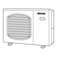
Drawings showing physical dimensions for specific outdoor unit models.

4. REFRIGERANT FLOW DIAGRAM

4-1. Refrigerant Flow Diagram

Diagram showing refrigerant circulation paths for SAP-CMRV1424EH.

5. PERFORMANCE DATA

5-1. Temperature Charts

Performance data related to various temperature conditions.

5-2. Heating Performance

Specific performance data for heating mode operation.

6. ELECTRICAL DATA

6-1. Electric Wiring Diagrams

Schematics detailing electrical wiring for outdoor units.

7. FUNCTIONS

7-1. Explanation of Functions

Detailed descriptions of operational modes like HEAT, COOL, and DRY.

7-2. Protective Functions

7-2-1. Defrost Detection and Release

Explanation of how the defrost cycle is managed.

7-2-2. Current Control

7-2-3. Low Start Current

7-2-4. Compressor Temperature Control

7-2-5. Control at HEAT Start-up

8. TROUBLESHOOTING

8-1. Precautions before Inspection or Repair

Essential safety measures before performing any service procedures.

8-2. Trouble Diagnosis by Error Monitor Lamps

8-2-2. Display of Error Monitor Lamps

Interpreting the meaning of error lamp codes for fault diagnosis.

8-3. Checking the Outdoor System

8-3-1. Checking the Outdoor Unit

Steps to check the outdoor unit's basic operational functions.

8-4. Trouble Diagnosis of Each Part

8-4-1. Problems of Each Part and Inspection Points

Common issues and their corresponding inspection points for diagnosis.

8-4-2. Inspection Points for Each Part

8-5. Trouble Diagnosis of Fan Motor

9. REFRIGERANT R410A: SPECIAL PRECAUTIONS WHEN SERVICING UNIT

9-1. Characteristics of New Refrigerant R410A

Properties, composition, and characteristics of R410A refrigerant.

9-2. Checklist before Servicing

Essential pre-service checks and considerations for R410A.

9-3. Tools Specifically for R410A

9-4. Tubing Installation Procedures

9-5. In Case of Compressor Malfunction

9-5-1. Procedure for Replacing Compressor

Step-by-step guide for replacing a faulty compressor.

9-6. In Case Refrigerant is Leaking

9-7. Charging Additional Refrigerant

9-8. Retro-Fitting Existing Systems

APPENDIX A INSTALLATION INSTRUCTIONS

IMPORTANT! Please Read Before Starting

Safe Installation & Operation Practices

Key steps for safe and efficient installation and operation.

Special Precautions Summary

Safety warnings for wiring, transport, installation, and servicing.

1. General Installation Overview

1-1. Tools Required for Installation

List of necessary tools not supplied with the unit.

1-2. Accessories Supplied with Unit

Items provided with the air conditioning unit.

1-3. Optional Copper Tubing Kit

Information on purchasing optional copper tubing kits.

1-4. Copper Tube and Insulation Material

Specifications for required tubing and insulation materials.

2. Installation Site Selection

2-1. Indoor Unit Site Selection

Criteria for selecting appropriate locations for indoor units.

2-2. Connecting Indoor Units

Connecting Indoor Unit for SAP-CMRV1424

Specific connection diagram for model SAP-CMRV1424.

2-3. Outdoor Unit Site Selection

2-4. Outer Dimensions of Outdoor Unit

2-5. Diagram of Outdoor Unit Installation

3. Installation Process

3-1. Embedding the Tubing and Wiring

Routing and securing tubes and wires during installation.

3-4. Flaring Procedure with a Flare Tool

Detailed steps for performing tube flaring for connections.

3-6. Tubing Connections

3-7. Insulation of Refrigerant Tubing

3-9. Finishing the Installation

4. AIR PURGING

Air Purging with a Vacuum Pump

Procedure for purging air and moisture using a vacuum pump.

■ Pump Down

5. Wiring Instructions

5-1. General Precautions on Wiring

Safety and general rules for performing electrical wiring.

5-3. Wiring System Diagram

5-4. How to Connect Wiring to the Terminal

5-5. Wiring Instructions for the Outdoor Unit

6. Test Run

8. Installation Check Sheet

APPENDIX B INSTALLATION INSTRUCTIONS

IMPORTANT! Please Read Before Starting

Safe Installation & Operation Practices

Key steps for safe and efficient installation and operation.

Special Precautions Summary

Safety warnings for wiring, transport, installation, and servicing.

1. General Installation Overview

1-1. Tools Required for Installation

List of necessary tools not supplied with the unit.

1-2. Accessories Supplied with Unit

Items provided with the air conditioning unit.

2. Installation Site Selection

2-1. Indoor Unit Site Selection

Criteria for selecting appropriate locations for indoor units.

2-2. Connecting Indoor Units

Connecting Indoor Unit for SAP-CMRV1924

Specific connection diagram for model SAP-CMRV1924.

2-3. Outdoor Unit Site Selection

2-4. Outer Dimensions of Outdoor Unit

2-5. Diagram of Outdoor Unit Installation

3. Installation Process

3-1. Embedding the Tubing and Wiring

Routing and securing tubes and wires during installation.

3-4. Flaring Procedure with a Flare Tool

Detailed steps for performing tube flaring for connections.

3-6. Tubing Connections

3-7. Insulation of Refrigerant Tubing

3-9. Finishing the Installation

4. AIR PURGING

Air Purging with a Vacuum Pump

Procedure for purging air and moisture using a vacuum pump.

■ Pump Down

5. Wiring Instructions

5-1. General Precautions on Wiring

Safety and general rules for performing electrical wiring.

5-3. Wiring System Diagram

5-4. How to Connect Wiring to the Terminal

5-5. Wiring Instructions for the Outdoor Unit

6. Test Run

8. Installation Check Sheet

APPENDIX B INSTALLATION INSTRUCTIONS

APPENDIX C UNIT COMBINATION TABLES

2-Room Outdoor Unit Combination Table

Compatibility table for 2-room configurations.

3-Room Outdoor Unit Combination Table

Compatibility table for 3-room configurations.

4-Room Outdoor Unit Combination Table

Compatibility table for 4-room configurations.

Related product manuals