Do you have a question about the Sanyo SAP-CMRV1424EH and is the answer not in the manual?
Safety precautions for wiring, transporting, installing, and servicing the unit.
Electrical shock hazard warning and wiring safety guidelines.
Guidelines for safe handling and moving of indoor and outdoor units.
Installation advice for ceilings, walls, rooms, moist locations, high winds, and snow.
Procedures for connecting refrigerant tubing, including flare method and torque.
Safety measures for servicing, including turning off power and keeping clear of moving parts.
General safety notes regarding ventilation and refrigerant gas.
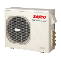
Installation instructions specific to the SAP-CMRV1424EH outdoor unit.
Installation instructions for SAP-CMRV1924EH, 1934EH, 2444EH, and 3144EH outdoor units.
Details connectable indoor units for the SAP-CMRV1424EH 2-room outdoor unit.
Details connectable indoor units for the SAP-CMRV1924EH 2-room outdoor unit.
Details connectable indoor units for the SAP-CMRV1934EH 3-room outdoor unit.
Details connectable indoor units for the SAP-CMRV2444EH 4-room outdoor unit.
Details connectable indoor units for the SAP-CMRV3144EH 4-room outdoor unit.
Detailed specifications for the outdoor unit SAP-CMRV1424EH.
Details on major components like compressor, fan, and heat exchanger for outdoor units.
Lists other components like sensors and their specifications, with resistance-temperature graphs.
Illustrates the refrigerant flow and provides insulation guidelines for tubing.
States that temperature chart data will be available in a future issue.
States that heating performance data will be available in a future issue.
Electric wiring diagrams for the outdoor unit SAP-CMRV1424EH.
Explains the operational logic and conditions for various modes like INITIAL and HEAT.
Details protective functions like defrost detection, release, and clean defrost.
Explains how current control limits operating frequency to prevent overloads.
Describes how low start current prevents flickering of lights during unit startup.
Details compressor temperature control to prevent overheating of the coil.
Explains startup frequency control for HEAT operation at low outdoor temperatures.
Crucial safety precautions for inspecting and repairing electronic control circuits.
Explains how error monitor lamps on the PCB indicate specific faults or sensor failures.
Procedures for checking the outdoor unit's power supply and defrost operation.
Identifies common problems and corresponding inspection points for various unit parts.
Diagnoses fan motor issues based on symptoms and provides troubleshooting steps.
Information on R410A refrigerant, its composition, and properties.
Guidelines and tools required for servicing with R410A refrigerant.
Lists specific tools required for servicing R410A refrigerant systems.
Provides instructions and notes on installing refrigerant tubing.
Outlines the procedure for replacing a malfunctioning compressor.
Details the steps for detecting, repairing, and recharging refrigerant after a leak.
Instructions for charging additional refrigerant, especially when extending tubes.
Guidelines for retrofitting existing units and tubing with R410A.
Lists valid combinations of indoor and outdoor units for the system.
Overview of installation procedures, tools, and materials.
Lists tools needed for installation that are not supplied with the unit.
Lists accessories provided with the unit.
Information about optional copper tubing kits for connecting units.
Specifies the type of copper tube and insulation material required for installation.
Lists additional materials needed for proper installation.
Guidelines for selecting appropriate locations for indoor and outdoor units.
Guidelines for selecting an appropriate installation site for the indoor unit.
Explains how to connect indoor units to the outdoor unit for specific models.
Provides guidelines and diagrams for selecting the installation site for the outdoor unit.
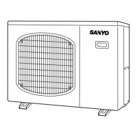
Shows diagrams with outer dimensions for various outdoor unit models.
Illustrates the recommended installation layout for indoor and outdoor units.
Step-by-step guide for the physical installation of the air conditioning system.
Instructions on routing and securing refrigerant tubing and wiring.
Guidance on using drain caps and elbows for the outdoor unit's drain hole.
Explains the flaring method for connecting refrigerant tubes.
Step-by-step procedure for performing flaring on copper tubes using a flare tool.
Instructions on insulating refrigerant tubing to prevent heat loss and condensation.
Guidance on taping refrigerant tubes and wiring bundles together.
Steps for sealing wall holes after insulation and taping to prevent drafts and rain.
Procedure for removing air and moisture from the refrigerant system.
Describes the process of air purging using a vacuum pump to remove air and moisture.
Explains the pump-down procedure for recovering refrigerant gas before relocation or disposal.
Guidelines and precautions for wiring the air conditioning system.
General safety precautions and guidelines for wiring the unit.
Provides recommendations for wire length, diameter, and fuse capacity based on model.
Wiring system diagrams illustrating connections between indoor and outdoor units.
Detailed instructions on how to connect wires to the unit's terminal plates.
Specific wiring instructions for connecting cables to the outdoor unit.
Procedures for performing a test run and checking tubing/wiring connections.
Instructions for connecting a Home Automation device to the indoor unit PCB.
A checklist to verify all installation steps have been correctly completed.
Electric wiring diagrams for various indoor and outdoor unit configurations.
| Refrigerant | R410A |
|---|---|
| Indoor Unit Weight | 24.3 lbs |
| Cooling Capacity | 14000 BTU/h |
| Voltage | 208/230V |
| Coefficient of Performance (COP) | 3.5 COP |