2
2-25
1
2
10s
20s
ON
12
ON
12
ON
12
ON
12
ON
12
ON
12
ON
OFF
ON
OFF
ON
OFF
ON
OFF
ON
OFF
ON
OFF
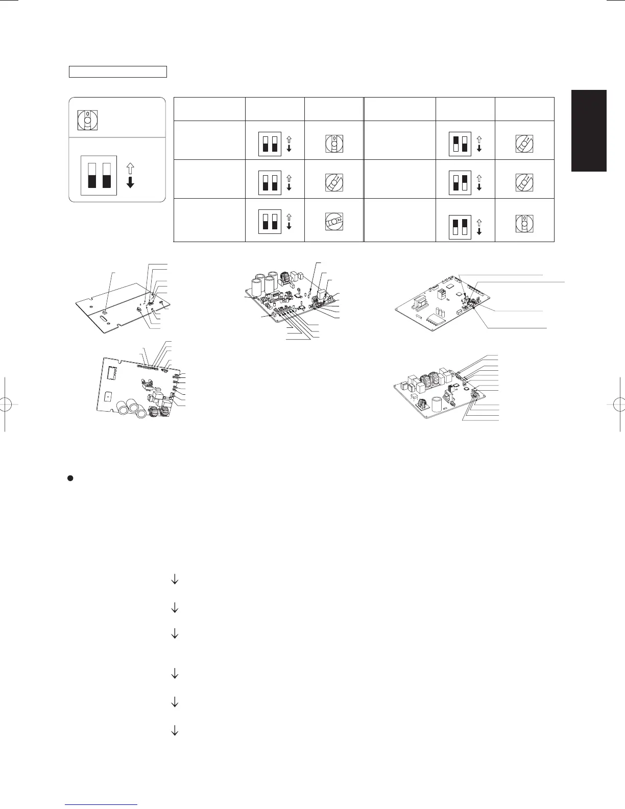
2-26-2. Setting the outdoor unit system addresses
For basic wiring diagram (Set the system addresses: 1, 2, 3...)
Fig. 2-24
Case 1
If the power can be turned ON separately for the indoor and outdoor units in each system:
(The indoor unit addresses can be set without running the compressor.)
Automatic address setting from the outdoor unit
(K type)
(1) Turn on the indoor and outdoor unit power for refrigerant system 1.
Press and hold the automatic address setting button (black) for 1 second or longer at the outdoor unit where the
power was turned ON.
The compressor operates when the power is turned ON at a different outdoor unit.
Communication for automatic address setting begins.
LED 1 and 2 on the outdoor unit control PCB blink alternately, and turn OFF when address setting is completed.
<Approximately 4 – 5 minutes are required.>
(2) Next, turn ON the power only at the indoor and outdoor units in a different system. Press the automatic address
setting button (black) on the outdoor unit.
LED 1 and 2 on the outdoor unit control PCB blink alternately, and turn OFF when address setting is completed.
Repeat the same procedure for each system and complete automatic address setting.
(3) Operation using the remote controller is now possible.
System
address No.
System address
10s digit
(2P DIP switch)
System address
1s place
(Rotary switch)
0
Automatic address
(Setting at shipment = “0”)
1
(If outdoor unit is No. 1)
2
(If outdoor unit is No. 2)
11
(If outdoor unit is No. 11)
21
(If outdoor unit is No. 21)
30
(If outdoor unit is No. 30)
Both OFF
Both OFF
Both OFF
10s digit ON
20s digit ON
10s digit and 20s
digit ON
“0” setting
“1” setting
“2” setting
“1” setting
“0” setting
“1” setting
System
address No.
System address
10s digit
(2P DIP switch)
System address
1s place
(Rotary switch)
Outdoor unit control PCB
System address rotary switch (Set to “0” at time of shipment)
System address rotary switch
System address
DIP switch
OFF
ON
ON
Up side
HIC
Temperature
sensor
AUTO ADD (CN041)
System address
Rotary switch (S002)
TERMINAL (S010)
JP007
System address
DIP switch (S003)
RC-P (CN032,RED)
LED1
LED2
PUMP DOWN (CN042)
EEPROM (IC006)
TO (CN022, WHT)
Bottom
side
C2 (CN020, WHT)
MOV (CN25, WHT)
C1 (CN021, BLK)
TD, TS (CN023, WHT)
EXCT (CN026, RED)
SILENT (CN028, WHT)
RC-P (CN032, RED)
FAN (CN030, WHT)
ROM (CN012, WHT)
OC (CN013, BLU)
EMG (CN014, BRN)
20S (CN09, WHT)
FUSE (25A, F003)
SPW-C486VH
F101
MOV
(CN025, WHT)
TD (CN024, BLK)
TO (CN023, BLK)
TS (CN022, RED)
Varistor (VA002)
JP007
Varistor (VA001)
Terminal plug
(CN015, BLK)
EMG (CN014, BRN)
OC (CN013, BLU)
ROM (CN012, WHT)
EEPROM (IC007)
PRY (CN110, YEL)
C2 (CN020, WHT)
C1 (CN021, WHT)
SPW-C256/366VH
System address rotary switch
Terminal plug (CN015, BLK)
OC (CN013, BLU)
EMG (CN014, BRN)
JP007
ROM (CN012, WHT)
EEPROM (IC007)
TD (CN024, BLK)
TO (CN023, BLK)
MOV(CN025, WHT)
SPW-C256/366VH8
SPW-C486/606VH8
System address 10s digit and 20s digit
DIP switch
Automatic address
button (black)
Terminal plug (black)
C2 (CN020, WHT)
C1 (CN021, WHT)
TS (CN022, RED)
SM830160-03ClassicPAC-iA4.ind2525SM830160-03ClassicPAC-iA4.ind2525 2010/02/1610:28:142010/02/1610:28:14
 Loading...