Do you have a question about the Sanyo SPW-CR363GVH8 and is the answer not in the manual?
| Brand | Sanyo |
|---|---|
| Model | SPW-CR363GVH8 |
| Category | Air Conditioner |
| Language | English |
Essential safety and operating guidelines before installation or service.
Guidelines for performing specific tasks like wiring and transporting the unit.
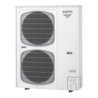
Details specifications for various outdoor unit models, including electrical, refrigerant, and dimensions.
Specifications for 4-way semi-concealed indoor units (X type), covering performance, electrical, and dimensions.
Specifications for floor-standing indoor units (F type), covering performance, electrical, and dimensions.
Specs for 1-way semi-concealed-slim indoor units (SL type), covering performance, electrical, and dimensions.
Explains how compressor capacity is controlled based on various factors and conditions.
Details the process of reverse cycle defrosting, including detection and execution conditions.
Explains how room temperature is controlled using thermostats and sensors, including mode switching.
Describes the automatic mode for switching between heating and cooling based on room temperature.
Guides users through diagnosing and solving common problems using error codes and flowcharts.
Provides diagrams showing the location of sensors and solenoid valves in outdoor and indoor units.
Illustrates the Printed Circuit Boards (PCBs) for indoor and outdoor units, showing component locations.
Details troubleshooting steps and methods for diagnosing compressor failures and replacement.
Step-by-step instructions for the safe removal and installation of a compressor.
Presents electrical data for various outdoor unit models, including wiring diagrams and symbols.
Presents electrical data for various indoor unit models, including wiring diagrams and symbols.


 Loading...