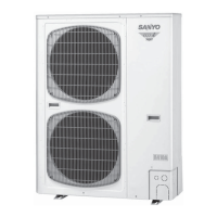
Do you have a question about the Sanyo MINI ECO-i SPW-CR365GXH56B and is the answer not in the manual?
| Category | Air Conditioner |
|---|---|
| Model | SPW-CR365GXH56B |
| Refrigerant | R410A |
| Power Supply | 3 Phase, 380-415V, 50Hz |
| Energy Efficiency Ratio (EER) | 3.2 |
| Coefficient of Performance (COP) | 3.6 |
| Noise Level (Indoor) | Varies depending on the connected indoor units |
Procedure for performing a test run of the system, including checks and settings.
Details on how to configure the indoor unit control PCB for operation.
Process for automatically assigning addresses to connected indoor and outdoor units.
Settings for performing a test run using the wired remote controller.
Basic functions for setting parameters like filter lifetime and addresses via remote.
Advanced functions for detailed system configuration via remote controller.
Overview and review of various remote controller functions and their settings.
Procedure to display sensor temperatures from the remote controller.
Procedure to view past failures and alarms from the remote controller.
Explanation of various alarm messages indicated by LEDs and on the remote controller.
Detailed information about the indoor unit control PCB components and functions.
Detailed information about the outdoor unit control PCB components and functions.
Introduction to the service checker tool for system monitoring and settings.
Overview of the functions available through the service checker display.
How to use the ordinary display for controls and monitoring operations.
Procedures for monitoring indoor and outdoor unit sensor temperatures.
How to recall and display the outdoor unit's alarm history.
How to access and change outdoor unit EEPROM settings via the service checker.
Explanation of the remote control interface and control items for indoor units.
Installation and wiring procedures for the outdoor parallel I/O interface.
How to output signals from the indoor unit control PCB.
Installation instructions and overview of the ON/OFF controller.
Installation instructions and overview of the system controller.
Operation manual for the intelligent controller, covering setup and usage.
Instructions for electrical installers on wiring, safety precautions, and accessories.
Safety precautions and installation guide for the local adaptor.
Product manual detailing the LonWorks interface for system integration.
Installation guidelines and parts supplied for the remote sensor.
Manual for setting programmed operations, schedules, and holidays.
Installation and wiring instructions for the serial-parallel I/O unit.
Installation and wiring instructions for the serial-parallel I/O unit.



 Loading...