EasyManua.ls Logo

Sanyo 2-WAY ECO-i SPW-C0705DXHN8 User Manual

Sanyo 2-WAY ECO-i SPW-C0705DXHN8
143 pages
To Next Page IconTo Next Page
Page #1 background imageLoading...
Page #1 background image
SERVICE MANUAL
85464849263000
2-WAY ECO-i
MULTI SYSTEM
REFERENCE NO.
SM830163-00
Outdoor Unit
Class 70 90 115 130 140
C Model Name
SPW-C0705DXHN8 SPW-C0905DXHN8 SPW-C1155DXHN8 SPW-C1305DXHN8 SPW-C1405DXHN8
SPW-C0705DXHN8R SPW-C0905DXHN8R SPW-C1155DXHN8R SPW-C1305DXHN8R SPW-C1405DXHN8R
Indoor Unit
Class 7 9 12 16 18 25 30 36 48 60
X
4-Way Air Discharge
Semi-Concealed
SPW-
XDR74GXH56(A/B)
X075XH
SPW-
XDR94GXH56(A/B)
X095XH
SPW-
XDR124GXH56(A/B)
X125XH
SPW-
XDR164GXH56(A/B)
X165XH
SPW-
XDR184GXH56(A/B)
X185XH
SPW-
XDR254GXH56(A/B)
X255XH
SPW-
XDR364GXH56(A/B)
X365XH
SPW-
XDR484GXH56(A/B)
X485XH
SPW-
XDR604GXH56(A/B)
X605XH
XM
4-Way Air Discharge
Semi-Concealed
SPW-
XM075XH
SPW-
XM095XH
SPW-
XM125XH
SPW-
XM165XH
SPW-
XM185XH
S
2-Way Air Discharge
Semi-Concealed
SPW-
SR74GXH56(A/B)
SPW-
SR94GXH56(A/B)
SPW-
SR124GXH56(A/B)
SPW-
SR164GXH56(A/B)
SPW-
SR184GXH56(A/B)
SPW-
SR254GXH56(A/B)
A
1-Way Air Discharge
Semi-Concealed
SPW-
ADR74GXH56B
SPW-
ADR94GXH56B
SPW-
ADR124GXH56B
L
1-Way Air Discharge
Semi-Concealed Slim
SPW-
LDR94GXH56(A/B)
SPW-
LDR124GXH56(A/B)
SPW-
LDR164GXH56(A/B)
SPW-
LDR184GXH56(A/B)
SPW-
LDR254GXH56(A/B)
U
Concealed-Duct
SPW-
UR74GXH56(A/B)
U075XH
UR74SXH56B
SPW-
UR94GXH56(A/B)
U095XH
UR94SXH56B
SPW-
UR124GXH56(A/B)
U125XH
UR124SXH56B
SPW-
UR164GXH56(A/B)
U165XH
UR164SXH56B
SPW-
UR184GXH56(A/B)
U185XH
UR184SXH56B
SPW-
UR254GXH56(A/B)
U255XH
UR254SXH56B
SPW-
UR304SXH56B
SPW-
UR364GXH56(A/B)
U365XH
UR364SXH56B
SPW-
UR484GXH56(A/B)
U485XH
UR484SXH56B
SPW-
UR604GXH56(A/B)
U605XH
UR604SXH56B
US
Concealed-Duct
SPW-
US075XH
SPW-
US095XH
SPW-
US125XH
SPW-
US165XH
SPW-
US185XH
T
Ceiling-Mounted
SPW-
TDR124GXH56(A/B)
T125XH
SPW-
TDR164GXH56(A/B)
T165XH
SPW-
TDR184GXH56(A/B)
T185XH
SPW-
TDR254GXH56(A/B)
T255XH
SPW-
TDR364GXH56(A/B)
T365XH
SPW-
TDR484GXH56(A/B)
T485XH
K
Wall-Mounted
SPW-
KR74GXH56(A/B)
K075XH
SPW-
KR94GXH56(A/B)
K095XH
SPW-
KR124GXH56(A/B)
K125XH
SPW-
KR164GXH56(A/B)
SPW-
KR184GXH56(A/B)
SPW-
KR254GXH56(A/B)
FM
Concealed Floor Standing
SPW-
FMR74GXH56(A/B)
SPW-
FMR94GXH56(A/B)
SPW-
FMR124GXH56(A/B)
SPW-
FMR164GXH56(A/B)
SPW-
FMR184GXH56(A/B)
SPW-
FMR254GXH56(A/B)
F
Floor Standing
SPW-
FR74GXH56(A/B)
SPW-
FR94GXH56(A/B)
SPW-
FR124GXH56(A/B)
SPW-
FR164GXH56(A/B)
SPW-
FR184GXH56(A/B)
SPW-
FR254GXH56(A/B)
GU
Total Heat Exchanger
with DX coil
SPW-
GU055XH
SPW-
GU075XH
SPW-
GU105XH
Class 25 36 48 76 96
D
Concealed-Duct
High-Static Pressure
SPW-
DR254GXH56(A/B)
SPW-
DR364GXH56(A/B)
SPW-
DR484GXH56(A/B)
SPW-
DR764GXH56(A/B)
SPW-
DR964GXH56(A/B)
W-2WAYECO-iSYSTEMCover.inddaW-2WAYECO-iSYSTEMCover.indda 2008/09/0416:07:462008/09/0416:07:46
Question and Answer IconNeed help?

Do you have a question about the Sanyo 2-WAY ECO-i SPW-C0705DXHN8 and is the answer not in the manual?

Sanyo 2-WAY ECO-i SPW-C0705DXHN8 Specifications

General IconGeneral
BrandSanyo
Model2-WAY ECO-i SPW-C0705DXHN8
CategoryAir Conditioner
LanguageEnglish

Summary

Section 1: CONTROL FUNCTIONS

Introduction

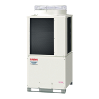
Provides a general overview of the W-2WAY ECO-i system and its capabilities.

Selecting Outdoor Unit for Operation

Outlines the rules and procedures for selecting and operating multiple outdoor units in the system.

Compressor Control

Details the control mechanisms and selection rules for compressors within the outdoor units.

Special Controls

Explains specific control functions such as 4-way valve adjustment and oil recovery.

Operation of Solenoid Valves

Describes the function and operation of various solenoid valves in the system.

Outdoor Unit Electronic Thermostatic Expansion Valves [MOV1, MOV2 & MOV4]

Details the types and operation of electronic thermostatic expansion valves used in outdoor units.

Outdoor Fan Control

Explains how the outdoor fan speed and operation are controlled under various conditions.

Demand Control

Describes the system's demand control functionality via serial-parallel I/O.

Indoor Unit Control of the Electronic Control Valve

Details the control of electronic control valves within indoor units during normal and special operations.

Discharge Temperature

Covers discharge temperature protection alarms and sensor failure detection for compressors.

Current Protection

Explains current protection mechanisms for fan motors and compressors, including alarm codes.

Pressure Sensor Failure

Details alarms related to high and low-pressure sensor failures and their causes.

Backup Operation

Explains automatic and manual backup operation procedures for system continuity during failures.

Service Maintenance Functions

Outlines EEPROM settings for noise countermeasures, drain pump, delayed start, and auto backup.

Section 2: OUTDOOR UNIT REPAIR PROCEDURES

Removing Panels

Provides instructions for removing front and power outlet/valve covers for access.

Removing Electrical Component Box and Duct

Details the process for removing the electrical component box, cover, and ducts.

Discharging Compressor Oil

Explains how to discharge compressor oil and check its condition for system assessment.

Backup Operation

Covers automatic and manual backup operation procedures for system continuity during repairs.

Recovering Refrigerant

Outlines procedures for recovering refrigerant from outdoor and indoor units for repair.

Checking for Leakage After Repair

Describes pressure checks and soapy water methods for detecting leaks after repairs.

Evacuating System

Details the process of evacuating the system to remove remaining refrigerant or gases.

Charging Compressor Oil

Explains how to charge compressor oil into the outdoor unit using specialized equipment.

Pumping Out Refrigerant from Outdoor Unit

Provides instructions for pumping out refrigerant from an outdoor unit before repairs.

Compressor

Covers compressor trouble diagnosis, replacement procedures, and dry core cleaning.

High and Low Pressure Sensors

Details the removal and installation procedures for high and low pressure sensors.

Replacing 4-way Valve

Explains how to replace the 4-way valve, including necessary precautions.

Section 3: OUTDOOR UNIT MAINTENANCE REMOTE CONTROLLER

Overview

Introduces the RCS-TM80BG outdoor unit maintenance remote controller and its purpose.

Functions

Lists the functions available through button operations and display information.

Ordinary Display Controls and Functions

Explains how to use the remote controller's display for unit start/stop, mode change, and test runs.

Monitoring Operations

Details how to use the remote controller to display sensor temperatures of indoor and outdoor units.

Outdoor Unit Alarm History Monitor

Explains how to check the outdoor unit's alarm history using the remote controller.

Mode Settings

Describes how to configure system settings using Setting Mode 1 and Setting Mode 2.

Section 4: REMOTE CONTROLLER FUNCTIONS

Simple Settings Function

Allows basic settings like filter lifetime, operating mode priority, and addresses for indoor units.

Detailed Settings Function

Provides advanced configuration options for system address, indoor unit settings, and temperature shifts.

Remote Controller Servicing Functions

Details servicing functions like test run, sensor display, and address changes for remote controller operations.

Section 5: TROUBLE DIAGNOSIS

Contents of Remote Controller Switch Alarm Display

Lists possible causes of malfunction based on wired and wireless remote controller displays.

Outdoor Unit Control Panel LED Display

Explains the meaning of LED indicators on the outdoor unit control panel for status and alarms.

Remote Controller Servicing Functions

Details how to use remote controller functions for diagnosis, including sensor temperature monitoring.

W-2WAY ECO-i Alarm Codes

Provides a comprehensive list of alarm codes, their meanings, probable causes, and checks.

Blinking Inspection Display on the Remote Controller

Explains blinking inspection displays related to automatic backup and compressor magnet SW seizing.

Inspection of Parts

Details methods for inspecting key components like high-pressure switches and electronic control valves.

Test Pin

Describes how to operate individual parts by short-circuiting test pins on the control PCB.

Related product manuals