EasyManua.ls Logo

Sanyo CH0951 User Manual

Sanyo CH0951
98 pages
To Next Page IconTo Next Page
Page #1 background imageLoading...
Page #1 background image
REFERENCE NO. SM700447
W
TECHNICAL & SERVICE MANUAL
KHS0951 / CH0951
KHS1251 / CH1251
KHS1852 / CH1852
SPLIT SYSTEM AIR CONDITIONER
FILE NO.
Indoor Model No. Product Code No.
KHS0951 1 852 069 13
KHS1251 1 852 069 14
KHS1852-S 1 852 069 15
Outdoor Model No. Product Code No.
CH0951 1 852 069 16
CH1251 1 852 069 17
CH1852 1 852 069 18
Indoor Unit Outdoor Unit
Destination: U.S.A.
KHS0951
KHS1251
KHS1852
CH0951
CH0952
CH1852
000-111 SM (1-17) 00.3.17 11:44 AM y[W A

Table of Contents

Other manuals for Sanyo CH0951

Question and Answer IconNeed help?

Do you have a question about the Sanyo CH0951 and is the answer not in the manual?

Sanyo CH0951 Specifications

General IconGeneral
Power Supply220-240V, 50Hz
RefrigerantR410A
Cooling Capacity9000 BTU
Operating Temperature (Cooling)18°C to 43°C
Noise Level (Outdoor)52 dB(A)

Summary

SPECIAL PRECAUTIONS

Wiring and Installation Safety

Safety guidelines for electrical, installation, and tubing tasks.

Unit Handling and Servicing

Safe practices for moving and maintaining the unit.

General Safety Warnings

Important safety warnings and cautions for unit operation.

OPERATING RANGE

SPECIFICATIONS

Unit Specifications

Technical details of indoor/outdoor units.

MAJOR COMPONENT SPECIFICATIONS

Indoor Unit Components

Specifications for indoor unit parts like PCB, motors.

Outdoor Unit Components

Specifications for outdoor unit parts like compressor, fan motor.

OTHER COMPONENT SPECIFICATIONS

Indoor Unit Components

Transformer and thermistor specs for indoor units.

Outdoor Unit Components

Thermistor, relay, thermostat, valve specs for outdoor units.

REFRIGERANT FLOW DIAGRAM

Refrigerant Flow Diagram

Visual representation of refrigerant cycle.

PERFORMANCE DATA

Performance Charts

Cooling and heating performance graphs.

Cooling Capacity

Detailed cooling capacity tables by condition.

Heating Capacity

Heating capacity chart based on outdoor temp.

ELECTRICAL DATA

Electrical Characteristics

Current, power input, and rating conditions.

Electric Wiring Diagrams

Wiring schematics for indoor and outdoor units.

Printed Circuit Board Layouts

Visual guide to PCB component placement.

INSTALLATION INSTRUCTIONS

Installation Site Selection

Guidelines for choosing indoor/outdoor unit locations.

Remote Control Unit Installation

Best practices for mounting the remote control.

Address Switches Setup

Setting address switches for multi-unit rooms.

Recommended Wire Length and Diameter

Guidelines for electrical wiring.

FUNCTION

Room Temperature Control

How the unit regulates room temperature.

Dry Operation and Auto Mode

Functionality of dry mode and auto mode.

Operational Protection Features

Prevents freezing, overheating, and protects compressor.

Cold Draft & Defrosting Operation

Prevents cold air and manages defrost cycles.

Low Temperature Heating Protection

Protects compressor in very low temps.

TROUBLESHOOTING

Initial Checks

Power, wiring, and connection checks.

Unit Not Operating

Troubleshooting for unit not starting or not running.

Partial Operation Issues

Issues with specific components like fans or compressor.

Abnormal Operation & Performance

Problems with cooling/heating modes or performance.

Sensor Defect Diagnosis

Troubleshooting sensor failures.

CHECKING ELECTRICAL COMPONENTS

Insulation Resistance Measurement

Procedures for checking insulation resistance.

Fuse and Capacitor Checks

How to check fuses and motor capacitors.

ELECTRICAL COMPONENT ARRANGEMENT

Indoor Unit Component Layouts

Diagrams showing component placement in indoor units.

Outdoor Unit Component Layouts

Diagrams showing component placement in outdoor units.

Features

Control & Operation Features

Unit control, auto modes, and restart capabilities.

Timer and Comfort Features

Features for comfort, air quality, and scheduling.

Product Information

Alert Symbols

Installation Location

Electrical Requirements

Safety Instructions

Names of Parts

Indoor Unit Components

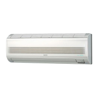
Identification of indoor unit parts.

Outdoor Unit Components

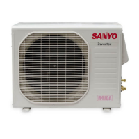
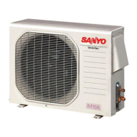
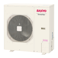
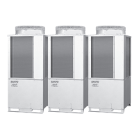
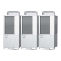
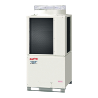
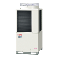
Identification of outdoor unit parts.

Unit Display and Operation Selector

Operation Selector and Indicators

Explains unit's operation selector and indicator lamps.

Remote Control Unit Symbols

Remote Control Unit Operation

Transmitter and Display Functions

Details on remote buttons and their display feedback.

Mode, Flap, and Fan Speed Controls

How to use mode, flap, and fan speed selectors.

Using the Remote Control Unit

Installing Batteries

Steps for inserting batteries into the remote.

Remote Control Unit Placement

Recommended locations for remote operation.

Operation with the Remote Control Unit

Automatic Operation

How to use the auto mode via remote.

Manual Operation

Steps for manual mode control.

Adjusting Fan Speed

Setting fan speed automatically or manually.

Night Setback Mode

Using the energy-saving setback feature.

Special Remarks

DRY Operation and Heating Details

Specifics of dry mode and heating performance.

Indicator Lamps and Normal Sounds

Meaning of indicator lamps and normal operational sounds.

Using the 12-Hour ON and OFF Timer

Setting 12-Hour Timers

Setting the unit to turn on or off after a delay.

Using the 1-Hour OFF Timer

1-Hour Timer Functionality

Setting a single hour auto-off timer.

Combining Timer Functions

Using 1-hr and 12-hr timers together.

Adjusting the Airflow Direction

Horizontal and Vertical Airflow

Manually adjusting horizontal vanes and flap settings.

Operation without the Remote Control Unit

Care and Cleaning

General Cleaning Precautions

Safety and general cleaning advice.

Anti-mold Filter Maintenance

Removing, cleaning, and replacing filters.

Air Cleaning Filter Installation

How to install optional air filters.

Tips for Energy Saving

Troubleshooting

Common Issues and Remedies

Table of common problems, causes, and solutions.

Operating Range

Related product manuals