Do you have a question about the Sanyo CH2442 and is the answer not in the manual?
Adjusts room temperature by controlling compressor ON/OFF based on thermostat input.
Controls indoor fan speed to prevent cold air draft until indoor heat exchange coils warm up.
Adjusts indoor fan speed automatically based on room temperature when AUTO mode is selected.
Selects outdoor fan speed automatically based on outdoor temperature to optimize performance.
Prevents the indoor heat exchange coil from freezing by regulating electronic refrigerant control valve.
Controls condensing temperature by sensing outdoor heat exchanger coil temperature.
Prevents the air conditioner from overloading, particularly during heating.
Prevents the compressor motor from burnout by controlling discharge gas temperature.
Automatically switches between heating and cooling modes based on room temperature relative to set temperature.
Operates defrosting system when frost forms on the outdoor coil to maintain performance.
Directs refrigerant flow in the correct direction based on the selected operation mode (Cooling/Heating).
Features a power failure recovery function to resume operation after power interruption.
Provides precise control of refrigerant flow amount for smooth heating/cooling adjustments.
Monitors compressor discharge gas temperature to prevent overheating and burnout.
Detects compressor current to stop the motor and prevent damage from overcurrent.
Controls refrigerant circulation volume via a pulse-type electronic valve based on multiple conditions.
Protects compressor and electrical components by monitoring power voltage levels.
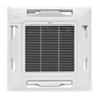
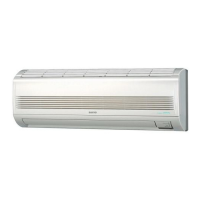
Provides electric wiring diagrams and schematic diagrams for various indoor unit types.
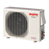
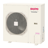
Provides electric wiring diagrams and schematic diagrams for outdoor units.
Guides users through diagnosing and solving unit problems using flow charts and alarm messages.
Details procedures for checking electrical components like resistance, fuses, and PCB settings.
Lists detailed technical specifications for each indoor and outdoor unit model.
Provides specifications for key internal components of indoor and outdoor units.
Lists specifications for various auxiliary components like transformers, motors, and sensors.
Provides detailed physical dimensions and mounting information for indoor and outdoor units.
Illustrates the refrigerant flow path during cooling and heating cycles for different models.
Specifies the acceptable indoor and outdoor temperature ranges for cooling and heating operation.
Presents cooling capacity data under various temperature and airflow conditions for different models.
Shows heating capacity data under various temperature conditions for different models.
Displays charts related to operating current, pressure, and fan speed based on conditions.
Provides octave band sound pressure level data for different unit types and models.
Explains how to increase fan speed to address low airflow due to high static pressure.
Illustrates air throw distance based on louver angle, fan speed, and room temperature.
Details tubing length limits, elevation differences, and refrigerant charging requirements.
| Type | Split System |
|---|---|
| Power Supply | 220-240V, 50Hz |
| Operating Temperature (Cooling) | 18°C to 43°C |
| Noise Level (Indoor) | 45 dB |
| Cooling Capacity | 24000 BTU/h |