EasyManua.ls Logo

Sanyo CH2472 User Manual

Sanyo CH2472
25 pages
To Next Page IconTo Next Page
Page #1 background imageLoading...
Page #1 background image
This air conditioner uses the new refrigerant R410A.
Refrigerant service valve size = 5/16"
NOTE
85264189989003 © SANYO 2007
SANYO Commercial Solutions In Canada
A Division of SANYO North America Corporation SANYO Canada Inc.
Cornerstone Business Park, 1-300 Applewood Crescent, Concord
1062 Thorndale Avenue, Ontario, L4K 5C7, Canada
Bensenville, IL 60106, U.S.A.
W
Contents
Page
IMPORTANT!
Please Read Before Starting .................................. 2
1. GENERAL .......................................................... 3
1-1. Tools Required for Installation (not supplied)
1-2. Accessories Supplied with Unit
1-3. Optional Copper Tubing Kit
1-4. Type of Copper Tube and Insulation Material
1-5. Additional Materials Required for Installation
2. INSTALLATION SITE SELECTION ................... 4
2-1. Indoor Unit
2-2. Outdoor Unit
3. HOW TO INSTALL THE INDOOR UNIT ............. 6
3-1. Remove the Rear Panel from the Unit
3-2. Make a Hole
3-3. Install the Rear Panel on the Wall
3-4. Remove the Grille to Install the Indoor Unit
3-5. Shape the Indoor Side Tubing
3-6. Wiring Instructions
3-7. Recommended Wire Length and Diameter
3-8. Wiring Instructions for Inter-unit Connections
3-9. Mounting
3-10. Drain Hose
4. HOW TO INSTALL THE OUTDOOR UNIT ....... 16
4-1. Wiring Instructions for the Outdoor Unit
5. REFRIGERANT TUBING .................................. 17
5-1. Use of the Flaring Method
5-2. Flaring Procedure with a Flare Tool
5-3. Caution before Connecting Tubes Tightly
5-4. Connecting Tubing between Indoor and
Outdoor Units
5-5. Insulation of Refrigerant Tubing
5-6. Taping the Tubes
5-7. Finishing the Installation
6. AIR PURGING................................................... 19
I Air Purging with a Vacuum Pump (for Test Run)
I Basic Functions of the Service Valves
I Pump Down
INSTALLATION INSTRUCTIONS
Model Combinations
Combine indoor and outdoor units only as listed
below.
Indoor Unit Outdoor Unit
KHS1872 CH1872
KHS2472 CH2472
Power Source:
60 Hz, single-phase, 230/208 V
– Inverter Split System Air Conditioner –
COOL/DRY/ HEAT Model
Be sure to read the yellow instruction sheet
attached to the outdoor unit for models using the
new refrigerant R410A.
The illustrations are based on the typical appearance of
a standard model. Consequently, the shape may differ
from that of the air conditioner that you are installing.
NOTE
7. REMOTE CONTROL UNIT INSTALLATION
POSITION ......................................................... 23
7-1. Mounting on a Wall
8. ADDRESS SWITCH .......................................... 24
8-1. Address Setting of the Remote
Control Unit
07-153 CH1872-2472 6/12/07 3:14 PM Page a
Question and Answer IconNeed help?

Do you have a question about the Sanyo CH2472 and is the answer not in the manual?

Sanyo CH2472 Specifications

General IconGeneral
BrandSanyo
ModelCH2472
CategoryAir Conditioner
LanguageEnglish

Summary

IMPORTANT! Safety and Precautions

Special Precautions for Installation

Critical safety warnings for wiring, transporting, and general installation practices.

General Information and Requirements

Installation Tools and Accessories

Lists required tools and supplied accessories for unit installation.

Copper Tubing and Materials

Details specifications for optional copper tubing kits and necessary materials.

Additional Installation Materials

Lists extra materials needed for installation, like tape and putty.

Installation Site Selection

Indoor Unit Placement Guidelines

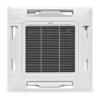
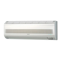
Provides recommendations and warnings for selecting the indoor unit location.

Outdoor Unit Placement Guidelines

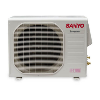
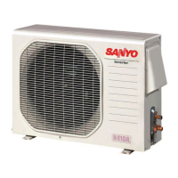
Offers advice and restrictions for choosing a suitable outdoor unit installation site.

Indoor Unit Installation

Unit Preparation and Wall Mounting

Covers rear panel removal, making wall holes, and mounting the rear panel securely.

Tubing, Wiring, and Grille Handling

Details grille removal, tubing shaping, wiring instructions, and wire length.

Final Mounting and Drain Hose Management

Instructions for mounting the unit, connecting tubing, and managing the drain hose.

Outdoor Unit Installation

Outdoor Unit Wiring Instructions

Details on connecting power supply and inter-unit wiring to the outdoor unit.

Refrigerant Tubing Installation

Flaring Method and Preparation

Explains the flaring technique and necessary precautions for connecting refrigerant tubes.

Connecting and Insulating Tubing

Covers tightening torque for connections, insulation requirements, and taping.

System Purging and Testing

Air Purging with Vacuum Pump

Procedure for removing air and moisture from the refrigerant system using a vacuum pump.

Air Conditioner Test Run

Steps to perform a test run of the air conditioner using the remote controller.

Service Valves and Pump Down

Explains service valve functions and the pump down procedure for maintenance.

Remote Control Unit Setup

Installation Position Guidelines

Recommends suitable and unsuitable locations for the remote control unit.

Wall Mounting Instructions

Detailed steps for mounting the remote control unit on a wall.

Remote Control Address Setting

Setting Remote Control Address

Procedure to change the remote controller's address to prevent interference.

Related product manuals