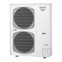
Do you have a question about the Sanyo SPW-CR903GV8 and is the answer not in the manual?
Guidance on proper installation in various locations and conditions.
Procedures and precautions for connecting refrigerant tubing, including flare method.
Safety precautions and general guidelines for servicing the unit.
Critical safety instructions for electrical wiring, emphasizing qualified personnel.
Advice on safely picking up and moving indoor and outdoor units.
Important considerations regarding refrigerant density limits in rooms for safety.
Table detailing various indoor unit types and their specifications.
Table detailing outdoor unit specifications, operating ranges, and connections.
Detailed specifications for the outdoor unit, including electrical and performance data.
Details of key components within the outdoor unit, such as compressor and fan motor.
Diagrams showing the external dimensions and mounting points of the outdoor unit.
Visual representation of the refrigerant path during operation cycles.
Graphs showing octave band sound pressure levels for various models.
Detailed specifications for the 4-way air discharge semi-concealed indoor units.
Key components of the 4-way semi-concealed indoor units, like fan motor and electronic valve.
Dimensions and mounting details for 4-way semi-concealed indoor units.
Noise level charts for different models of 4-way semi-concealed indoor units.
Detailed specifications for 2-way air discharge semi-concealed indoor units.
Component details for 2-way semi-concealed indoor units, including fan motor and electronic expansion valve.
Dimensions and mounting information for 2-way semi-concealed indoor units.
Noise level graphs for various 2-way semi-concealed indoor unit models.
Detailed specifications for 1-way air discharge semi-concealed indoor units.
Component details for 1-way semi-concealed indoor units like fan motor and electronic expansion valve.
Dimensional drawings and mounting details for 1-way semi-concealed indoor units.
Noise charts for different models of 1-way semi-concealed indoor units.
Detailed specifications for wall-mounted indoor units.
Component details for wall-mounted indoor units, including fan motor and electronic expansion valve.
Dimensional drawings and mounting information for wall-mounted indoor units.
Noise level graphs for various wall-mounted indoor unit models.
Detailed specifications for ceiling-mounted indoor units.
Component details for ceiling-mounted indoor units, including fan motor and electronic expansion valve.
Dimensional drawings and mounting details for ceiling-mounted indoor units.
Noise charts for different ceiling-mounted indoor unit models.
Detailed specifications for concealed duct indoor units.
Component details for concealed duct indoor units, including fan motor and electronic expansion valve.
Dimensional drawings and mounting information for concealed duct indoor units.
Noise level graphs for various concealed duct indoor unit models.
Detailed specifications for concealed duct high static pressure indoor units.
Component details for high static pressure concealed duct units, including fan motor and electronic valve.
Dimensional drawings and mounting details for high static pressure concealed duct units.
Noise charts for different high static pressure concealed duct indoor unit models.
Detailed specifications for floor-standing indoor units.
Component details for floor-standing indoor units, including fan motor and electronic expansion valve.
Dimensional drawings and mounting information for floor-standing indoor units.
Noise level graphs for various floor-standing indoor unit models.
Detailed specifications for concealed floor-standing indoor units.
Component details for concealed floor-standing indoor units, including fan motor and electronic valve.
Dimensional drawings and mounting information for concealed floor-standing indoor units.
Noise charts for different concealed floor-standing indoor unit models.
Detailed specifications for 1-way semi-concealed slim indoor units.
Component details for 1-way semi-concealed slim indoor units, including fan motor and electronic valve.
Dimensional drawings and mounting information for 1-way semi-concealed slim indoor units.
Noise level graphs for various 1-way semi-concealed slim indoor unit models.
Explanation of how compressor capacity is managed through various controls.
Details on protection mechanisms for compressors and other components.
How frost is detected on the heat exchanger to initiate defrost.
Conditions under which the defrost cycle is executed.
Criteria for terminating the defrost operation.
Initial checks for wiring and power supply before proceeding with troubleshooting.
Flowcharts to identify problems and their causes for cooling and heating modes.
Detailed explanation of various alarm codes displayed on the remote controller.
Correlation between outdoor PCB LEDs and specific fault conditions.
Troubleshooting steps based on observed symptoms and related parts.
Step-by-step procedures for diagnosing and fixing components that are not functioning.
How to use the remote controller for service checks like test runs and sensor readings.
Diagram showing sensor and solenoid locations on the outdoor unit.
Diagrams illustrating sensor and solenoid placement within various indoor units.
Procedures for setting switches on PCBs and performing test runs.
Alarm messages related to incorrect wiring or setup.
Alarm messages indicating specific unit malfunctions.
Steps for diagnosing compressor issues and checking its components.
Criteria and procedures for replacing compressors.
Electrical wiring diagrams and symbols for outdoor units.
Electrical wiring diagrams and symbols for various indoor unit types.
| Brand | Sanyo |
|---|---|
| Model | SPW-CR903GV8 |
| Category | Air Conditioner |
| Language | English |


 Loading...