EasyManua.ls Logo

Sanyo SPW-X483GH56 User Manual

Sanyo SPW-X483GH56
105 pages
To Next Page IconTo Next Page
Page #1 background imageLoading...
Page #1 background image
INDOOR MODEL No. PRODUCT CODE No. OUTDOOR MODEL No. PRODUCT CODE No.
SPW-X253GH56 854 011 35 SPW-C253GH5 854 012 18
SPW-X253GH56 854 011 35 SPW-C253GH8 854 012 19
SPW-X363GH56 854 011 36 SPW-C363GH8 854 012 20
SPW-X483GH56 854 011 37 SPW-C483GH8 854 012 21
FILE NO.
SERVICE MANUAL
1
2
3
4
5
Section
85464849133001 REFERENCE NO. SM830033
SPW-X253GH56 ⁄ SPW-C253GH5
SPW-X253GH56 ⁄ SPW-C253GH8
SPW-X363GH56 SPW-C363GH8
SPW-X483GH56 SPW-C483GH8
SPLIT SYSTEM AIR CONDITIONER
SPW-C253GH5
SPW-C253GH8
SPW-X253GH56
0407_X_S
SPW-X363GH56
SPW-X483GH56
SPW-C363GH8
SPW-C483GH8
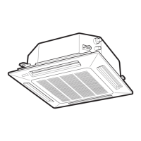
Indoor Unit Outdoor Unit
0406_X_S
0408_C_S
0409_C_S

Table of Contents

Other manuals for Sanyo SPW-X483GH56

Questions and Answers:

Sanyo SPW-X483GH56 Specifications

General IconGeneral
RefrigerantR410A
Compressor TypeRotary
Cooling Capacity48000 BTU
Power Supply220V-240V, 50Hz
TypeSplit Type
Outdoor Unit Noise Level58 dB

Summary

Specifications

Unit Specifications

Detailed technical specifications for various indoor and outdoor unit models.

Major Component Specifications

Specifications for key components like motors, coils, and compressors.

Other Component Specifications

Specifications for secondary components like transformers and thermistors.

Dimensional Data

Physical dimensions and installation layout information for indoor and outdoor units.

Refrigerant Flow Diagram

Visual representation of the refrigerant path during cooling and heating cycles.

Operating Range

Defines the environmental temperature and humidity limits for unit operation.

Processes and Functions

Room Temperature Control

Explains how the unit regulates room temperature via compressor operation.

Cooling Cycle Functions

Details freeze prevention and condensing temperature control in cooling mode.

Heating Cycle Functions

Covers cold draft prevention, overload protection, and defrosting in heating.

Compressor and System Protection

Mechanisms for protecting the compressor from overload and voltage issues.

Control Valve and Operation Modes

Functions of the 4-way valve, electronic refrigerant valve, and auto mode.

Other Operational Functions

Describes dehumidifying, auto-flap, and drain pump operations.

Electrical Data

Indoor Unit Wiring and Schematics

Electric wiring diagrams and schematic diagrams for the indoor unit.

Outdoor Unit Wiring and Schematics

Electric wiring diagrams and schematic diagrams for the outdoor unit.

Service Procedures

Troubleshooting and Error Codes

General troubleshooting steps, flow charts, and alarm message meanings.

Symptom Analysis and Component Repair

Guides for identifying issues based on symptoms and repairing components.

Electrical Component Testing Methods

Procedures for testing insulation resistance, protective devices, and electrical parts.

Sensor, PCB, and Remote Control Configuration

Diagrams, curves, settings for sensors, PCBs, and remote control functions.

Related product manuals