EasyManuals Logo

Sanyo SPW-X605H User Manual

Sanyo SPW-X605H
517 pages
To Next Page IconTo Next Page
To Previous Page IconTo Previous Page
Page #436 background imageLoading...
Page #436 background image
4-10
4
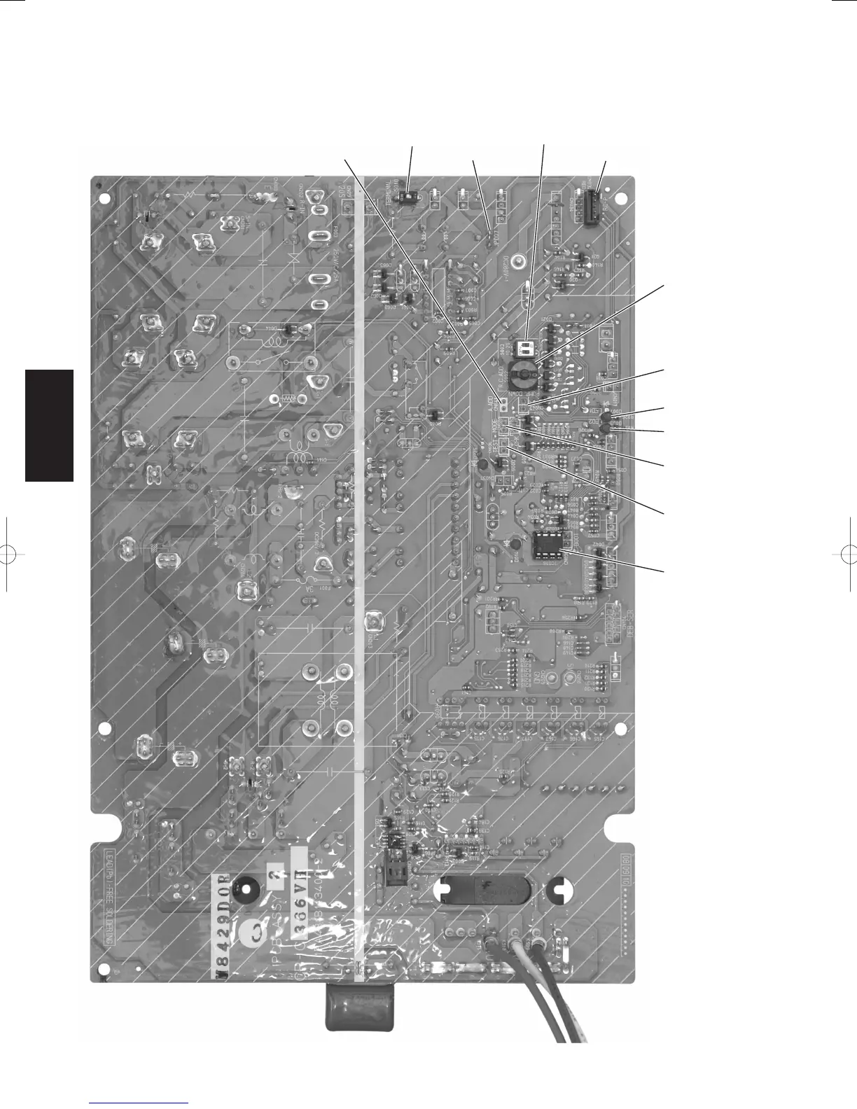
4-2. Outdoor Unit Control PCB
(2-1) Layout Diagram (CR-C366VH:Up side)
A.ADD pin
(CN041)
TERMINAL
(S010)
JP007
R.C.ADD
(S003)
RC-P
(CN032)
R.C.ADD
(S002)
PUMP DOWN pin
(CN042)
LED1
LED2
MODE pin
(CN031)
TEST pin
(CN036)
EEPROM
(IC006)
TERMINAL
PUMP DOWN pin
MODE pin
TEST pin
EEPROM
SM830160-03ClassicPAC-iA4.ind1010SM830160-03ClassicPAC-iA4.ind1010 2010/02/1610:29:332010/02/1610:29:33

Table of Contents

Questions and Answers:

Question and Answer IconNeed help?

Do you have a question about the Sanyo SPW-X605H and is the answer not in the manual?

Sanyo SPW-X605H Specifications

General IconGeneral
TypeSplit System
Cooling Capacity6.0 kW
Power Supply220-240V, 50Hz
RefrigerantR410A
Indoor Unit Noise Level42 dB(A)
Outdoor Unit Noise Level52 dB(A)
Indoor Unit Weight14 kg
Outdoor Unit Weight48 kg

Related product manuals