1-8. ADJUSTING SPECIFICATION
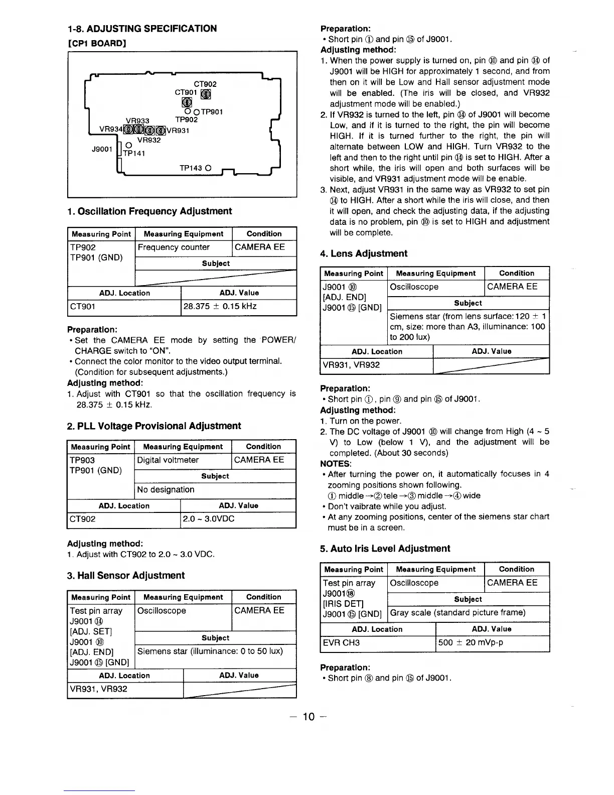
[CP1 BOARD]
“OO’kL-J
1. Oscillation Frequency Adjustment
Meaauring Point Meaeuring Equipment
Condition
TP902 Frequency counter
CAMERA EE
TP901 (GND)
I
Subject
—
—
I
ADJ. Location
I
ADJ. Value
I
I CT901
128.375 i 0.15 kHz I
Preparation:
● Set the CAMERA EE mode by setting the POWER/
CHARGE switch to “ON”.
● Connect the color monitor to the video output terminal.
(Condition for subsequent adjustments.)
Adjusting method:
1. Adjust with CT901 so that the oscillation frequency is
28.375 & 0.15 kHz.
2. PLL Voltage Provisional Adjustment
Meaeuring Point
Meaeuring Equipment
Condition
TP903
Digital voltmeter CAMERA EE
TP901 (GND)
Subiect
No designation
ADJ. Location
ADJ. Value
I CT902
12.0- 3.OVDC
I
Adjusting method:
1.Adjust with CT902 to 2.0 -3.0 VDC.
3. Hall Sensor Adjustment
Meaeuring Point
Meaeuring Equipment
Condition
Test pin array Oscilloscope
CAMERA EE
J9001 @
[ADJ. SET]
I
J9001 @
Subject
[ADJ. END]
Siemens star (illuminance: Oto 50 Iux)
J9001 @ [GND1
ADJ. Location
ADJ. Value
VR931 , VR932
Preparation:
● Short pin @ and pin @ of J9001.
Adjusting method:
1.When the power supply is turned on, pin @ and pin @ of
J9001 will be HIGH for approximately 1 second, and from
then on it will be Low and Hall sensor adjustment mode
will be enabled. (The iris will be closed, and VR932
adjustment mode will be enabled.)
2. If VR932 is turned to the left, pin @ of J9001 will become
Low, and if it is turned to the right, the pin will become
HIGH. If it is turned further to the right, the pin will
alternate between LOW and HIGH. Turn VR932 to the
left and then to the right until pin @ is set to HIGH. After a
short while, the iris will open and both surfaces will be
visible, and VR931 adjustment mode will be enable.
3. Next, adjust VR931 in the same way as VR932 to set pin
@to HIGH. After a short while the iris will close, and then
it will open, and check the adjusting data, if the adjusting
data is no problem, pin @ is set to HIGH and adjustment
will be complete.
4.
Lens Adjustment
Measuring Point
J9001 @
[ADJ. END]
J9001 @ [GND]
Measuring Equipment
Condition
Oscilloscope ICAMERA EE
Subject
Siemens star (from lens surface:120 + 1
cm, size: more than A3, illuminance: 100
to
200 Iux)
ADJ. Location
ADJ. Value
VR931 , VR932
Preparation:
● Short pin 0, pin @l and pin @ of J9001.
Adjusting method:
1. Turn on the power.
2. The DC voltage of J9001 @ will change from High (4 -5
V) to Low (below 1 V), and the adjustment will be
completed. (About 30 seconds)
NOTES:
● After turning the power on, it automatically focuses in 4
zooming positions shown following.
@ middle =@tele =@ middle ~@
wide
● Don’t vaibrate while you adjust.
● At any zooming positions, center of the siemens star chart
must be in a screen.
5. Auto Iris Level Adjustment
Measuring Point I
Measuring Equipment Condition
Test pin array 10scilloscope I CAMERA EE I
J9001 @
I
[IRIS DET]
Subject
J9001 @ [GND] Gray scale (standard picture frame)
ADJ. Location
ADJ. Value
EVR CH3
I500 t 20 mVp-p
I
Preparation:
● Short pin @ and pin @ of J9001.
–lo–
 Loading...