2-12. PW2 CIRCUIT (For VM-EX550P/560P)
[PW2 BOARD]
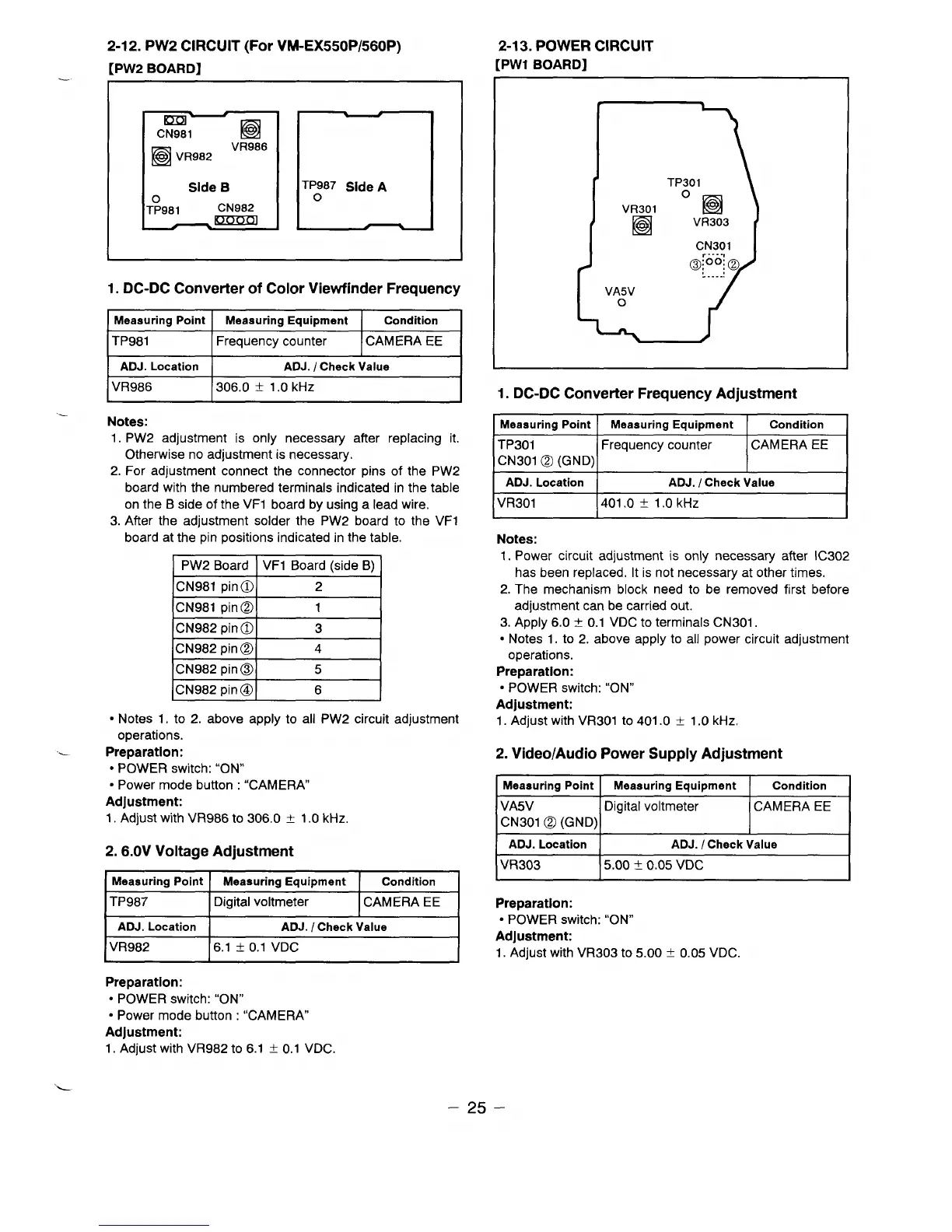
2-13. POWER CIRCUIT
[PW1 BOARD]
*
m
+
CN981
❑
❑
VR982 ‘R’88
Side B
T:981
CN982
1. DC-DC Converter of Color Viewfinder Frequency
Meaauring Point
Meaauring Equipment
Condition
I
ITP981 lFrequency counter I CAMERA EE I
I ADJ. Location I
ADJ. I
Check Value
I
IVR986
1306.0 i I.c)ld-lz
I
Notes:
1. PW2 adjustment is only necessary after replacing it.
Otherwise no adjustment is necessary.
2. For adjustment connect the connector pins of the PW2
board with the numbered terminals indicated in the table
on the B side of the VF1 board by using a lead wire.
3. After the adjustment solder the PW2 board to the VF1
board at the pin positions indicated in the table.
PW2 Board
VF1 Board (side B)
CN981 pin o
2
CN981 pin@
1
CN982 pin 0
3
CN982 pin@
4
CN982 pin@
5
CN982 pin@
6
● Notes 1. to 2. above apply to all PW2 circuit adjustment
operations.
..-
Preparation:
● POWER switch: “ON”
● Power mode button : “CAMERA
Adjustment:
1.
Adjust with VR986 to 306.0 + 1.0 kHz.
2. 6.OV Voltage Adjustment
Meaauring Point Meaauring Equipment
Condition
TP987
Digital voltmeter CAMERA EE
ADJ. Location ADJ. / Check Value
VR982
6.1 ~ 0.1 VDC
Preparation:
● POWER switch: “ON”
● Power mode button : “CAMERA
Adjustment:
1. Adjust with VR982 to 6.1 f 0.1 VDC.
CN301
,. ...,
VA5V
o
1. DC-DC Converter Frequency Adjustment
Measuring point I
Measuring Equipment
Condition
I
TP301 Frequency counter CAMERA EE
CN301 @ (GND)
I
1
1
I
ADJ. Location
ADJ. / Check Value
I
VR301
401,0 t 1.0 kHz
Notes:
1. Power circuit adjustment is only necessary after IC302
has been replaced. It is not necessary at other times.
2, The mechanism block need to be removed first before
adjustment can be carried out.
3. Apply 6.0 f 0.1 VDC to terminals CN301.
● Notes 1. to 2. above apply to all power circuit adjustment
operations.
Preparation:
● POWER switch: “ON”
Adjustment:
1. Adjust with VR301 to 401.0 t 1.0 kHz.
2. Video/Audio Power Supply Adjustment
Measuring Point I Measuring Equipment Condition
I
VA5V
Digital voltmeter
CAMERA EE
CN301 @ (GND)
ADJ. Location
ADJ. / Check Value
IVR303
15.00 ~ 0.05 VDC
I
Preparation:
● POWER switch: “ON”
Adjustment
1.
Adjust with VR303 to 5.oO ~ 0.05 VDC.
–25–
 Loading...