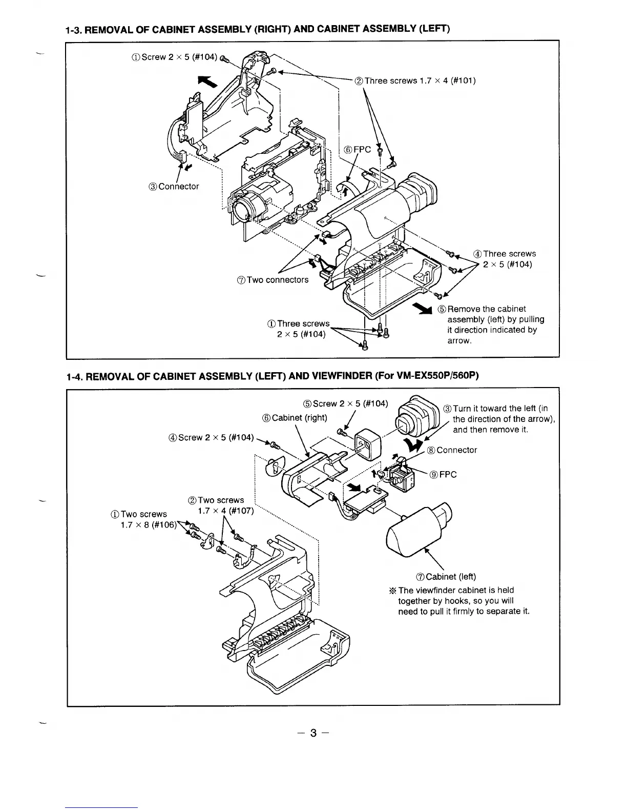
1-3. REMOVAL OF CABINET ASSEMBLY (RIGHT) AND CABINET ASSEMBLY (LEFT)
----
@Screw 2 x 5 (#104)
@Three screws 1.7 x 4 (#101)
I
@
‘\
f
Y
c.
‘-.. .
4
c
.
“\.
-y
.!
,,. ,
>
“;’
@Three screws
4
/’--”’
2 x 5 (#l 04)
“\ >,
“%3
~ @Remove the cabinet
@)Three screws
y~
+
assembly (left) by pulling
2 x 5 (#1 04)
it direction indicated by
arrow,
J
1-4. REMOVAL OF CABINET ASSEMBLY (LEIT) AND VIEWFINDER (For VM-EX550P/560P)
(D
toward the left (in
ection of the arrow),
@Screw 2 x 5 (#104)
en remove it.
@Two screws
Two screws
UXEW106)S:K)
@Cabinet (left)
X The viewfinder cabinet is held
together by hooks, so you will
need to pull it firmly to separate it.
–3–
 Loading...