EasyManuals Logo

Sanyo VPC-E10 Service Manual

Sanyo VPC-E10
55 pages
To Next Page IconTo Next Page
To Previous Page IconTo Previous Page
Page #13 background imageLoading...
Page #13 background image
13
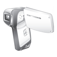
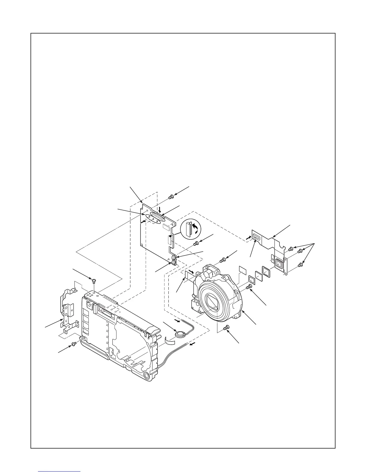
2-2. REMOVAL OF CP1 BOARD AND LENS
1. Remove the solder. (speaker)
2. Remove the solder. (microphone)
3. Speaker, 8
4. Remove the solder.
5. FPC
6. Connector
7. Two screws 1.4 x 2
When assembling,
tighten the screws order.
A B
When assembling,
tighten the screws order.
A B C
When assembling,
tighten the screws order.
a b c
8. Holder strap
9. Two screws 1.4 x 3
10. CP1 board
11. Three screws 1.6 x 5
12. Lens
13. Three screws 1.6 x 3
14. Assy, flexible pwb comp 3
1
2
3
4
5
6
7
8
9
9
10
11
11
11
12
13
14
A
B
C
a
b
c
7
A
B
4

Other manuals for Sanyo VPC-E10

Questions and Answers:

Question and Answer IconNeed help?

Do you have a question about the Sanyo VPC-E10 and is the answer not in the manual?

Sanyo VPC-E10 Specifications

General IconGeneral
BrandSanyo
ModelVPC-E10
CategoryDigital Camera
LanguageEnglish

Related product manuals