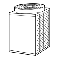
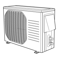
10
1-9. System Limitations
Max. No. allowable connected outdoor units 3 *1
Max. capacity allowable connected outdoor units 288,000 BTU/h (30 hp, 84.3 kW)
Max. connectable indoor units 40
Max. allowable indoor/outdoor capacity ratio 50 – 130 %
*1: Up to 3 units can be connected if the system has been extended.
1-7. Straight Equivalent Length of Joints
Design the tubing system by referring to the following table for the straight equivalent length of joints.
Table 1-8 Straight Equivalent Length of Joints
Gas tubing size (in. (mm))
1/2"
(12.7)
5/8"
(15.88)
3/4"
(19.05)
7/8"
(22.22)
1"
(25.4)
1-1/8"
(28.58)
1-3/8"
(34.92)
1-5/8"
(41.28)
90° elbow
1 1.1 1.4 1.6 1.7 1.9 2.5 2.8
45° elbow 0.8 0.9 1 1.2 1.3 1.4 1.8 2.0
U-shape tube bent (R2-3/8" – 4" (60 – 100)) 3 3.4 4.1 4.7 5.1 5.6 7.4 8.4
Trap bend
7.5 9.2 10.5 12.5 14.1 15.4 19.2 22.3
Y-branch distribution joint Equivalent length conversion not needed.
Ball valve for service Equivalent length conversion not needed.
Table 1-9 Refrigerant tubing (Existing tubing can be used.)
Tubing size (in. (mm))
Material O Material 1/2H • H
ø1/4" (ø6.35) t1/32" (t0.8) ø7/8" (ø22.22) t5/128" (t1.0)
ø3/8" (ø9.52) t1/32" (t0.8) ø1" (ø25.4) t5/128" (t1.0)
ø1/2" (ø12.7) t1/32" (t0.8) ø1-1/8" (ø28.58) t5/128" (t1.0)
ø5/8" (ø15.88) t5/128" (t1.0) ø1-1/4" (ø31.75) t3/64" (t1.1)
ø3/4" (ø19.05) over t5/128" (t1.0) ø1-1/2" (ø38.1) over t3/64" (t1.15)
ø1-5/8" (ø41.28) over t3/64" (t1.20)
* When bending the tubes, use a bending
radius that is at least 4 times the outer
diameter of the tubes.
In addition, take sufficient care to avoid
crushing or damaging the tubes when
bending them.
1-8. Additional Refrigerant Charge
Additional refrigerant charge amount is calculated from the liquid tubing total length and a type of outdoor unit as follows.
Liquid tubing size Amount of additional
(in. (mm)) refrigerant charge (oz/ft.)
ø1/4" (ø6.35) 0.279
ø3/8" (ø9.52) 0.602
ø1/2" (ø12.7) 1.38
ø5/8" (ø15.88) 1.99
ø3/4" (ø19.05) 2.78
ø7/8" (ø22.22) 3.93
Required amount of additional refrigerant charge = [(Amount of additional refriger-
ant charge per ft. of each size of liquid tube × its tube length) + (...) + (...)] + [Nec-
essary amount of additional refrigerant charge per outdoor unit + (...) + (...)]
* Always charge accurately using a scale for weighing.
* If the existing tubing is used, and the amount of on-site additional refrigerant
charge exceeds the value listed below, then change the size of the tubing to
reduce the amount of refrigerant.
Max. additional charge for 1 outdoor unit :62 lbs
Max. additional charge for 2 outdoor units :111 lbs
Unit: ft.
Table 1-11 System Limitations
Table 1-10-1 Amount of Additional Refrigerant Charge Per ft., According to Liquid Tubing Size
Table 1-10-2 Necessary Amount of Additional Refrigerant Charge Per Outdoor Unit
Further charge a certain amount listed below in addition to the amount of refrigerant charge.
CHDX07263, CHDXR07263 CHDX09663, CHDXR09663
42 oz/unit 42 oz/unit

 Loading...


