EasyManua.ls Logo

Sanyo XHS1271 User Manual

Sanyo XHS1271
123 pages
To Next Page IconTo Next Page
Page #1 background imageLoading...
Page #1 background image
TECHNICAL & SERVICE MANUAL
XHS1271 & PNR-XS1872 + CH1271
XHS1872 & PNR-XS1872 + CH1872
DC INVERTER SPLIT SYSTEM AIR CONDITIONER
Indoor Unit
Destination: North America
Outdoor Model No.
CH1271
CH1872
Product Code No.
1 852 330 22
1 852 330 38
Outdoor Unit
XHS1271 (Body) & PNR-XS1872 (Panel)
XHS1872 (Body) & PNR-XS1872 (Panel)
Wireless Remote Controller
Wired Remote Controller
(Option)
CH1271
CH1872
REFERENCE NO. SM700766
Indoor Model No.
Body (Panel)
XHS1271 (PNR-XS1872)
XHS1872 (PNR-XS1872)
Product Code No.
Body (Panel)
1 852 352 08 (1 852 352 11)
1 852 352 07 (1 852 352 11)
FILE NO.
Body
Panel

Table of Contents

Question and Answer IconNeed help?

Do you have a question about the Sanyo XHS1271 and is the answer not in the manual?

Sanyo XHS1271 Specifications

General IconGeneral
Indoor Unit Weight9 kg
Outdoor Unit Weight30 kg
Power Supply220V, 50Hz
RefrigerantR410A
Cooling Capacity12000 BTU/h

Summary

DC INVERTER SPLIT SYSTEM AIR CONDITIONER

Important Safety Information

Essential safety precautions and initial setup guidelines for proper operation.

Special Precautions

Wiring and Installation Safety

Specific warnings for wiring, installation, servicing, and handling.

Operating Range

Specifications

Unit Specifications

Detailed specifications for cooling and heating capacity, electrical ratings, and features.

Major Component Specifications

Indoor Unit Components

Detailed specifications for indoor unit parts like PCB, fan motor, and drain pump.

Outdoor Unit Components

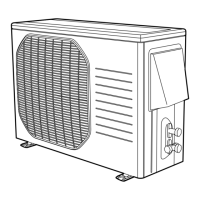
Detailed specifications for outdoor unit parts like compressor and fan motor.

Other Component Specifications

Dimensional Data

Refrigerant Flow Diagram

Refrigerant Flow Diagram

Visual representation of the refrigerant circuit and tubing insulation guidelines.

Performance Data

Cooling Capacity Performance Charts

Charts detailing cooling performance based on temperature.

Heating Capacity Performance Charts

Charts detailing heating performance based on temperature.

Electrical Data

Electrical Characteristics

Running amperes and power input for cooling and heating.

Electric Wiring Diagrams

Maintenance

Remote Control Address Setting

Guide to setting the address for multiple remote controls.

Outdoor Unit Connector Handling

Instructions for safely disconnecting and connecting connectors.

Disassembly Procedure

Step-by-step guide for disassembling indoor unit parts.

Functions

Operation Functions

Explains emergency, auto, and manual operation modes.

Protective Functions

Details overload, freeze, and compressor protection mechanisms.

Troubleshooting

Precaution Before Inspection/Repair

Safety warnings and precautions before starting troubleshooting.

Method of Self-Diagnostics

Procedure to activate and interpret self-diagnostic modes.

Checking Indoor and Outdoor Units

Trouble Diagnosis of Fan Motor

Noise Malfunction and Electromagnetic Interference

Checking Electrical Components

Insulation Resistance Measurement

How to measure insulation resistance for power supply, indoor, and outdoor units.

Fuse Continuity Check

Method to check fuse continuity on the PCB assembly.

Refrigerant R410A: Special Precautions

Characteristics of New Refrigerant R410A

Information on R410A refrigerant properties and components.

Checklist Before Servicing

Checklist and precautions before servicing with R410A.

Tools Specifically for R410A

Specific tools required for servicing R410A systems.

Tubing Installation Procedures

Guidelines for installing tubing, including flare procedures.

Handling Compressor Malfunctions

Procedures for replacing a malfunctioning compressor.

Handling Refrigerant Leaks

Steps for detecting, repairing, and recharging refrigerant leaks.

Related product manuals