Do you have a question about the SANYU SY8000-0R7G-2 and is the answer not in the manual?
General safety information categorized into Danger and Caution for inverter operation.
Important considerations and warnings for using the inverter in various scenarios.
Explains the naming convention for SY8000 series inverter models.
Details the information found on the inverter's nameplate.
Lists different SY8000 series inverter models and their specifications.
Provides detailed technical specifications for the SY8000 series inverters.
Shows outline diagrams and dimensions for inverter installation.
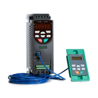
Lists available optional accessories for the SY8000 series inverter.
Outlines daily maintenance procedures for the inverter.
Provides guidance on selecting the appropriate SY8000 inverter model.
Covers environmental requirements and physical mounting of the inverter.
Details wiring, circuit breakers, and contactors for electrical setup.
Illustrates overall connection modes for the inverter and its peripherals.
Explains the main circuit terminals and their connections.
Details the control circuit terminal layout and functions.
Provides solutions for electromagnetic compatibility issues.
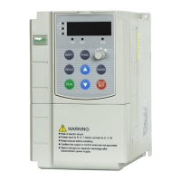
Explains the inverter's operation panel, buttons, and indicator lamps.
Describes operational procedures like parameter setting and fault reset.
Explains how to view inverter parameters in different states.
Provides a flowchart for quick inverter setup and adjustment.
Presents a comprehensive table of function parameters and their descriptions.
Continues the parameter table, detailing human-machine interface and start/stop control parameters.
Continues parameter table, covering parameter selection and display settings.
Continues parameter table, detailing start/stop control and input/output terminal parameters.
Continues parameter table, focusing on input/output terminal and protection function parameters.
Continues parameter table, detailing protection function and wobble frequency parameters.
Continues parameter table, covering protection functions and PID control.
Continues parameter table, detailing PID function and multi-speed control parameters.
Continues parameter table, covering multi-speed and serial communication parameters.
Continues parameter table, detailing motor parameter settings.
Explains basic function parameters like speed control mode and frequency selection.
Details the settings for V/F curves used for different load types.
Explains how to increase torque for low-frequency operation.
Configures the inverter's motor running direction.
Sets jump frequency to avoid mechanical resonance.
Assigns functions to the JOG key.
Configures the stop function behavior for the STOP/RST key.
Controls how keyboard and terminal UP/DOWN affect frequency settings.
Defines the display priority for local and external keyboards.
Selects which parameters are shown on the display during operation.
Selects which parameters are shown on the display when the inverter is stopped.
Sets the inverter's stop behavior (deceleration or free stop).
Defines stop modes including direct start, DC brake start, and rotary speed tracking start.
Sets the upper limit for analog input terminal 4.
Sets the upper limit for analog input terminal 5.
Configures the output type for terminal 2 (analog voltage/current).
Determines if terminal functions are active upon power-up.
Assigns functions to multifunctional input terminal 11.
Configures protection against over-voltage during deceleration.
Sets the voltage threshold for over-voltage stalling protection.
Selects the type of motor overload protection.
Sets the current threshold for motor overload protection.
Configures the level for automatic current limiting.
Records the running frequency when a current fault occurs.
Sets the range for jump frequency operation.
Introduces the PID control function for process automation.
Selects the source for the PID feedback signal.
Selects the source for the PID target quantity.
Sets the proportional gain for PID control.
Explains the multi-speed control functionality.
Sets the frequency for multi-speed step 0.
Configures the communication baud rate for serial communication.
Sets the data bit check mode for communication.
Sets the proportional gain for the speed ring in vector control.
Adjusts slip compensation for vector control accuracy.
Initiates motor parameter self-learning for optimal performance.
Selects the inverter type (Constant Torque or Fan/Pump).
Lists fault codes, symptoms, possible causes, and remedies for inverter faults.
Outlines daily checks and cleaning procedures for the inverter.
Details periodic inspection and cleaning tasks for the inverter.
Specifies when to replace components like fans and capacitors.
Describes the structure and format of the communication protocol.
Explains how the inverter connects to a network using the protocol.
Details the hardware and transmission modes of the communication bus.
Provides general instructions for using the communication protocol.
Explains the format of communication frames for RTU and ASCII modes.
Details command codes for reading and writing data via communication.
Explains the command code for writing data in communication.
Discusses errors related to bit and data checks in communication frames.
Describes how the inverter responds to errors during communication.
Lists error codes and their corresponding meanings for communication errors.