Data Interface
Purpose
Your balance/scale comes equipped with an
interface port for connection to a computer
or other peripheral device. You can use an
on-line computer to change, start and/or
monitor the functions of the balance/scale
and the application programs.
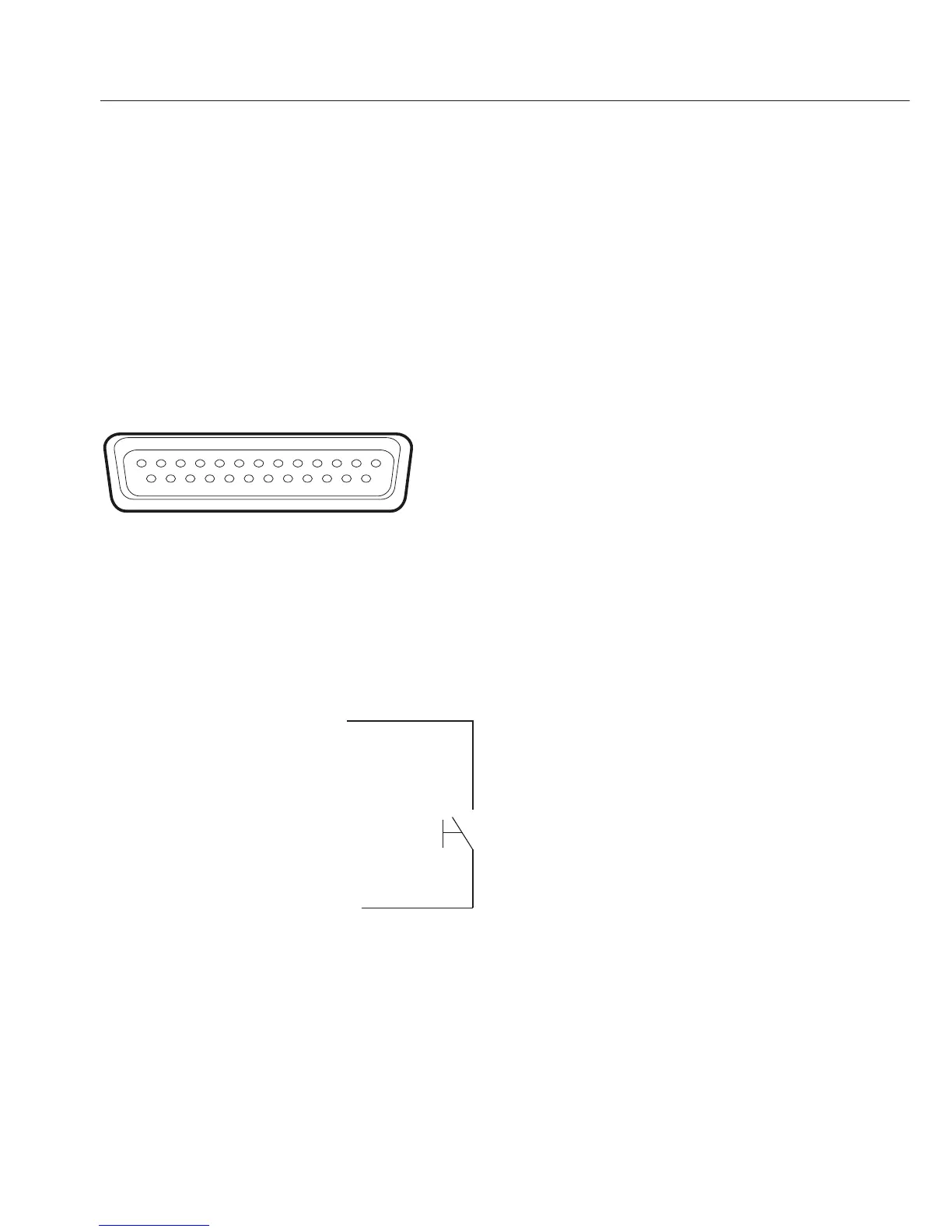
Female interface connector
Pin Assignment Chart, 25-pin
female interface connector, RS-232:
Pin 1: Shield
Pin 2: Data output (TxD)
Pin 3: Data input (RxD)
Pin 4: Internal ground (GND)
Pin 5: Clear to Send (CTS)
Pin 6: Not connected
Pin 7: Internal ground (GND)
Pin 8: Internal ground (GND)
Pin 9: Not connected
Pin 10: Not connected
Pin 11: +12 V
(operating voltage
for Sartorius printer) For remote switch
Pin 12: Reset _ Out *)
Pin 13: +5 V output
Pin 14: Internal ground (GND)
Pin 15: Universal remote switch
Pin 16: Not connected
Pin 17: Not connected
Pin 18: Not connected
Pin 19: Not connected
Pin 20: Data Terminal Ready (DTR)
Pin 21: Not connected
Pin 22: Not connected
Pin 23: Not connected
Pin 24: Not connected
Pin 25: +5 V output
*) = Hardware restart
46
Preparation
You can set these parameters for other
devices in the Setup menu (see the chapter
entitled “Configuring the Balance/Scale”).
You will also find a detailed description
of the available data interface commands
in the file “Data Interface Descriptions for
ED, GK and GW Models”, which you can
download from the Sartorius website
(www.sartorius.com “Download Center”).
The many and versatile properties of these
balances/scales can be fully utilized for
printing out records of the results when you
connect your balance/scale to a Sartorius
data printer. The recording capability for
printouts makes it easy for you to work
in compliance with ISO/GLP.