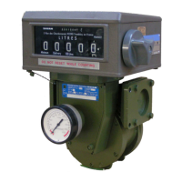
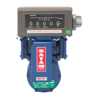
The SATAM BULKMETER ZC 17-12 is a positive displacement meter designed for accurate liquid measurement, suitable for various petroleum products. It is available in both mechanical and electronic configurations, offering flexibility for different operational needs.
Function Description
The core of the ZC 17-12 is its blade-type positive displacement measurement chamber, type MA 21. Liquid enters the metering unit, setting the rotor assembly in motion under pressure. A precise quantity of liquid is captured between consecutive blades and measured as it is pushed towards the outlet manifold. Accuracy is ensured by the minimal clearance between the rotor, stator, blades, and covers. The curved design of the manifolds and rotor promotes a steady, non-fluctuating flow, minimizing head loss. The rotor is supported on stainless steel ball bearings for durability and smooth operation.
In the mechanical configuration, the rotor's movement is transmitted to an AB35 calibrating mechanism via an AB40 transmission device. This allows for meter adjustment without requiring gear replacement. A meter head and an accumulative ticket printer, which can be reset and linked to the register, complete the mechanical setup.
For the electronic configuration, the MA 21 measurement chamber is coupled with an AC 30 impulse transmitter and an MPC electronic computer. This setup provides electronic measurement and data processing capabilities.
The meter can be equipped with a preset mechanism, either the XAD 39 mechanical preset valve or the XAD 54 pneumatic preset valve, to control the dispensed quantity. A 3-way valve, fitted at the meter outlet, allows for measured distribution through two different pipes, ensuring secure and precise measurement for either pipe. This ball-valve design prevents contact between the two outlets and includes a locking system linked to the meter head to prevent modification of the valve position during distribution or liquid flow through an unselected outlet.
Important Technical Specifications
- Measurement Chamber: Type MA 21, positive displacement, blade-type.
- Transmission Device (Mechanical): AB40, including AB35 calibrating mechanism.
- Electronic Components (Electronic): AC 30 impulse transmitter, MPC electronic computer.
- Preset Valves: XAD 39 mechanical preset valve or XAD 54 pneumatic preset valve.
- 3-Way Valve: Ball-valve type, 90° elbow body, 180° rotation with neutral closure.
- Adjustment Precision (AB35): Each notch of the adjustment screw equals a correction of 0.25%, with a maximum adjustment of 40%.
- Filtration Requirements:
- Jet A1: 50 microns
- Gasoline, Premium, Super: 70 microns
- Diesel oil, Gas oil, FOD: 200 microns
- Low Flow Initiation: Approximately 30 litres from the end of delivery for ZC 17-24 or 48 meters.
Usage Features
- Installation: Meters are supplied with counter flanges for connection to a 2" horizontal installation (Ø 60.3). Flow direction must align with the arrow on the AB40 transmission device cover. Upstream strainers are mandatory.
- Starting Operation: Ensure clean product, free of metallic particles. All piping must be clean, rinsed, and dry, free of air. Operation should be initiated progressively, respecting the maximum flow limit.
- Preset Operation:
- To display the required preset quantity, press the "Set" button to unlock, then use the 5 push buttons to set the desired quantity in litres.
- For emergency stop, press the "Stop" button.
- To open the preset valve, pull the control lever towards yourself.
- Low Flow Setting: The low flow rate can be adjusted by removing the cover and rotating an eccentric using a 19 mm flat spanner and a 10 mm spanner. Clockwise rotation increases the low flow rate, while anticlockwise rotation reduces it. A non-closing valve may indicate a too-low low flow rate setting. In the stop state, there must be clearance between the roller and the cam.
- 3-Way Valve Operation:
- Insert a ticket into the ticket printer.
- Choose the desired outlet pipe (front (B) or back (A)) by lightly pulling the lever (1) and positioning it, then placing lever (2) in an open position 0.
- Block the ticket printer by turning the meter head button one full turn. This action locks the ticket, prints the first line of figures, resets the register figures, and locks the selected 3-way valve setting.
- Delivery can commence, and the flow rate can be modified using the control lever (2).
- At the end of delivery, turn the meter head push button a full turn. This prints a second row of figures, releases the ticket, and releases the 3-way valve (without altering the register display). The cycle can then repeat.
- Adjustment Procedure:
- Perform a test run at maximum flow rate using a 500-litre gauge.
- Note volumes from the indicating device and the gauge.
- Calculate the difference.
- Unseal and remove the cover (1).
- Unscrew the two screws (2).
- Open the cover from the bottom.
- Adjust the calibration screw (3) by turning it the appropriate number of notches (difference in % / 0.25 = number of notches). For electronic calculators (RUBIS, EQUALIS L, EQUALIS MPC), refer to specific calibration instructions (U513237, U516318, U516703).
- Perform a new gauging test to check adjustment.
- Replace the cover and tighten screws.
- Re-seal.
Maintenance Features
- General: Periodic maintenance is required at least once a year. Operations requiring unsealing must be performed by a Company approved by Weights and Measures.
- Important Note: High-pressure water jets should not be used to clean the measuring unit, as this can cause serious damage.
- Quarterly Periodic Inspections (by user):
- Strainer Baskets: Inspect strainers installed upstream of the meter.
- Measurement Chamber MA21-12: Check for any leakage around the measuring chamber (piping, covers, outlet shaft). Leakage from the outlet shaft would be visible on the lower part of the AB40 transmission device.
- Ticket Printer: Ensure no particles or pieces of ticket are caught in the mechanism.
- Yearly Inspections:
- Measurement Chamber MA21-12: The chamber itself does not require preventive maintenance. Any necessary intervention must be carried out by a SATAM-approved repairer using approved test equipment.
- Mechanical Indicating Device: Refer to the Installation and Operation Manual for specific maintenance.
- Transmission Device AB40:
- Worm screw and gear (1 & 2): Check clearance, clean, and grease.
- Bearings (4 & 5) on shaft (3): Check wear, clean, and grease.
- Upper part of AB40: Check rings and drive gear shaft leading to the mechanical indicating device, clean, and grease the drive gears assembly.
- AB35 Adjustment Device: Does not require preventive maintenance.