Do you have a question about the Satelec Implant Center 2 and is the answer not in the manual?
Specifies user qualifications and potential interactions with other devices for safe operation.
Details important safety precautions, user restrictions, and potential device interactions.
Guidelines for safe device operation, environmental considerations, and maintenance.
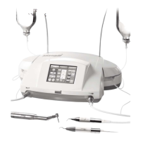
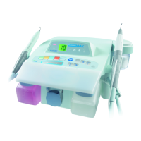
Identification of the main physical components of the Implant Center 2.
Overview of technical aspects and the LCD touch screen interface.
Details on controls and displays specific to PIEZOTOME, NEWTRON, and I-SURGE functions.
Description of pages for adjusting contra-angle, speed, and torque settings.
Information regarding the device startup sequence.
Overview of the TOOLBOX function for adjustments and resets.
Description of control unit sides, front panel, and footswitch.
Footswitch definitions and operational details for PIEZOTOME and NEWTRON modes.
Summary of technical specifications, protection, and safety devices.
Specifications for device dimensions, operating temperatures, humidity, and pressure.
Steps for unpacking, recommendations for connection, and physical installation.
Procedures for device startup and managing program settings.
Detailed control of irrigation: flush/prime, flow rate adjustment, and ON/OFF.
Setting rotation direction and adjusting program parameters for I-SURGE.
Steps to access and select I-SURGE programs and their parameters.
Procedure for programming custom contra-angle settings.
How to select pre-programmed or customize contra-angle settings.
Detailed steps for adjusting motor speed using the interface.
Detailed steps for adjusting motor torque using the interface.
Critical information for customizing PIEZOTOME function power levels and programs.
Summary of PIEZOTOME programs (D1-D4) and their main functions.
Key requirements for configuring NEWTRON function settings, including handpiece connection.
How to select programs and adjust power levels for the NEWTRON function.
Using Toolbox for adjustments like brightness, time-out, audio, and factory reset.
Adjusting audio volume, screen brightness, and light off time-out.
Procedures for storing settings and resetting the device to factory configurations.
Information on software version and factory settings for I-SURGE mode.
Safety measures for the I-SURGE micro-motor, including temperature monitoring.
Critical instructions for safe device operation, including connections and instrument handling.
Steps for safely shutting down and disconnecting the Implant Center 2.
Crucial information regarding device shutdown for cleaning and sterilization procedures.
Maintenance guidelines for sterile (disposable) and sterilizable irrigation lines.
Key warnings about cleaning agents and non-sterilizable parts of the device.
Procedures for cleaning, disinfecting, and sterilizing micromotor and scaler cords.
Critical warnings about cleaning agents, disassembly, and lubrication for the I-SURGE micro-motor.
Procedures for rinsing, cleaning, and disinfecting ultrasonic handpieces.
Guidelines on tip lifetime, monitoring, and procedures for cleaning and drying.
Importance of monitoring the device and recommendations for micro-motor inspection.
Step-by-step instructions for replacing fuses in the device's power receptacle.
A table listing common operational faults, their possible causes, and remedies.
Detailed troubleshooting steps for various faults, including spray, motor, and ultrasonic functions.
Crucial advice on keeping cords separated and avoiding interference with telecommunication devices.
Information on the Implant Center 2's electromagnetic emissions and compliance.
Details on the device's immunity to electrostatic discharge, transients, surges, and voltage variations.
Guidelines for maintaining minimum separation distances from radiofrequency emitters.
Multilingual list of symbols for common device functions and issues.
Symbols related to footswitch modes and storing settings.
Symbols representing PIEZOTOME programs and their functions.
Symbols for controlling audio level, screen brightness, and time-out.
Symbols for factory configuration, documentation reference, and electrical safety.
Identification details of the manufacturer, SATELEC, and its parent company, Acteon Group.
List of global subsidiaries and their contact information.
Contact details for SATELEC offices in the UK, Middle East, China, Philippines, and Thailand.
Contact details for SATELEC offices in Korea, India, Costa Rica, Russia, and Australia/New Zealand.
| Brand/Manufacturer | Satelec |
|---|---|
| Model | Implant Center 2 |
| Display | LCD screen |
| Type | Dental Implant System |
| Irrigation Flow Rate | 150 ml/min |
| Programs | Multiple pre-set programs |
| Control | Foot pedal |
| Power Supply | 100-240 V, 50/60 Hz |
| Torque Range | 5 to 80 Ncm |