EasyManua.ls Logo

Satronic MMG 810.1 - User Manual

Satronic MMG 810.1
4 pages
Print Icon
To Next Page IconTo Next Page
Loading...
1
A Honeywell Company
MMG 810.1 / 811.1
For 2-stage forced draught and combi oil/gas
burners
Suitable flame detectors:
- Ionisation probe
- UV sensor
- Infra-red flicker detector
INTRODUCTION
The MMG burner control box is capable of controlling
and monitoring forced draught and combi oil/gas burners
of any nominal rating (tested and approved as per EN 298).
The MMG 810.1 model 33 control boxes are also suitable for
use in stationary warm air generators (Direct air heaters
according to DIN 4794).
Different type and model designations identify the control
boxes according to varying national standards, and to some
extent, according to programme times.
TYPES AVAILABLE
MMG 810.1 Mod. 32 Art. Nr. 0640120
Mod. 33 Art. Nr. 0640220
Mod. 43 Art. Nr. 0642520
Mod. 45 Art. Nr. 0642620
MMG 811.1 Mod. 33 Art. Nr. 0640520
Mod. 63 Art. Nr. 0640420
ONSTRUCTIONAL FEATURES
The control box is enclosed in a protective, flame resistant,
transparent, plug-in type plastic housing, and includes:
Synchronous motor with reduction gearing driving cam
switch
Cam switch with informative, coloured programme in-
dicator
12-way cam switch assembly controlling the programme
sequence
Electronic components on plug-in printed circuit
The following important indicators and operating controls
are situated on the front of the control box:
Reset button incorporating signal lamp for malfunction
(lockout)
Coloured programme indicator
Central screw fastening
Burner Control Box
TECHNICAL DATA
Supply voltage 220 / 240 V (-15... +10%)
50 Hz (50 - 60 Hz)
AC frequency variations result in proportional timing
deviations
Fuse rating max. 10 A rapid, 6 A slow
Power consumption 10 VA
Max. current per output
term. 3 2A, cos ϕ 0.2
term. 4, B 2A, cos ϕ 0.4
term. 5, 6, C 1A, cos ϕ 0.4
Total load 5A, cos ϕ 0.4
Amplifier sensitivity 1 µA
Min. current from UV tube
or ionisation probe 5 µA
Flame detector cable max. 20 m cable length
Air proving switch 1 terminal 4 A, 230 V
Reset delay none
Flame detector
- Ionisation probe
- Infra-red flicker detector IRD 1020.1 end-on
- UV tube type UVZ 780 red markings
installed radially or axially
Infra red flare detector IRD 1020
Weight incl. base 350 g
Mounting attitude any
Insulation standard IP 44
Permissable ambient temp. -20° C... +60° C
Classified acc. to EN 298 BTLLXN
For external resetting, the remote reset device FR 870
(art. No. 70700) can be utilized. (Refer to doc. 750).
program timings (sec.) MMG 810.1 811.1
Model 32 33 43 45 33 63
Waiting time
at start-up tw 9 9 9 9 9 6
Max. reaction
time for air
proving switch tlw 6 6 6 6 6 5
Pre-purge time tv1 24 24 40 40 24 55
Pre-ignition time tvz 3 3 3 3 3 3
T. ignition time tz 6 6 6 8 6 5.5
Safety time ts 2 3 3 5 3 3
Time delay
term.6 / term.C tv2 10 10 10 10 10 6
EN1C-0142SZ20 0305
Question and Answer IconNeed help?

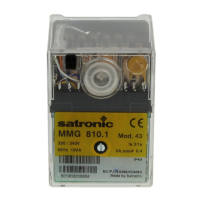
Do you have a question about the Satronic MMG 810.1 and is the answer not in the manual?

Summary

Introduction

Types Available

Instructional Features

Motor and Cam Switch Mechanism

Describes the synchronous motor, reduction gearing, and cam switch operation.

Programme Indicator and Sequence Control

Details the cam switch with its indicator and the 12-way assembly for sequence control.

Plug-in Electronic Components

Mentions the electronic components housed on a plug-in printed circuit.

Front Panel Indicators and Controls

Highlights key front-panel elements like the reset button, programme indicator, and fastening.

Technical Data

Electrical Supply and Frequency

Specifies supply voltage, frequency variations, and fuse rating.

Performance Specifications

Details power consumption, output currents, total load, and amplifier sensitivity.

Flame Detection and Detector Cable

Information on flame detector types, minimum UV tube current, and cable length limits.

System Parameters and Classification

Covers air proving switch, reset delay, ambient temperature, and EN 298 classification.

Technical Features

Flame Detection Methods

Describes compatible flame detectors: ionisation, UV sensor, and infra-red flicker.

Burner Control and Voltage Protection

Explains low-voltage protection, restart behavior, and terminal 5 load requirement.

Safety and Standards Compliance

Notes conformity to European standards and regulations.

Installation Guidelines

Details wiring base terminals, mounting, and general installation considerations.

Commissioning and Maintenance

Important Pre-Commissioning Checks

Emphasizes wiring checks, correct fuse rating, and ensuring normal shutdown cycles.

Functional Checks

Outlines required tests for manual valve, flame failure, and air pressure monitor.

Troubleshooting Common Issues

Provides guidance for burner failure to operate and fault condition triggers.

Schematic Connection and Process Diagrams

MMG 810.1 Diagram and Component Key

Presents the wiring diagram and process for MMG 810.1 with a component legend.

MMG 811.1 Diagram and Component Key

Presents the wiring diagram and process for MMG 811.1 with a component legend.

IRD Flame Detector Connection

Shows the specific wiring connections for the IRD 1020.1 flame detector.

Component Dimensions and Flame Signal Check

MMG Control Box and Socket Dimensions

Provides physical dimensions for the MMG control box and its associated socket.

Flame Detector Holder Dimensions

Details the dimensions for UVZ 780 and IRD 1020.1 flame detector holders.

Flame Signal Measurement

Illustrates how to check the flame signal strength for UVZ 780.

Ordering Information

Lists item numbers and designations for control boxes, sockets, and detectors.

Satronic MMG 810.1 Specifications

General IconGeneral
ModelMMG 810.1
ManufacturerSatronic
Frequency50/60 Hz
Temperature Range-20°C to +60°C
Operating Temperature-20°C to +60°C
Protection ClassIP40
TypeBurner Control Unit
Supply Voltage220-240 V AC
Mains Voltage220-240 V AC
Suitable forGas burners
Flame DetectorUV
Safety Time TS3 seconds
Power ConsumptionApprox. 5 VA

Related product manuals