1
A Honeywell Company
certified Qualitysystem
ISO 9001 / EN 29001
Reg. Nr. 10529
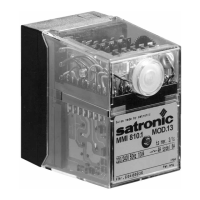
MMI 810.1 / 811.1
Gas burner automatic
safety control
For 2-stage forced draught and combi oil/
gas burners
Possible flame detectors:
- Ionization probe
- Infrared flicker detector
INTRODUCTION
The gas burner automatic safety control MMI controls
and monitors blown gas- and combined burners of any
nominal thermal load (tested and certified according to
EN 298).
The automatic safety controls MMI 810.1 models 13, 33 and
35 can also be utilized for burners on fixed hot air heaters
(Direct air heaters according to DIN 4794).
Various types and model designations differentiate the
automatic safety controls with respect to the programme
times, as well as with regard to differing national standards.
TYPES AVAILABLE
MMI 810.1 Mod. 13 * Art. Nr. 0620720
Mod. 33 Art. Nr. 0620220
Mod. 35 Art. Nr. 0620920
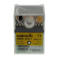
Mod. 43 Art. Nr. 0622520
Mod. 55 Art. Nr. 0621320
MMI 811.1 Mod. 35 Art. Nr. 0621120
Mod. 63 Art. Nr. 0620420
* Must only be used on boilers or other applications where
the 10 second pre-purge time is sufficient to provide at
least 3 volume changes of the combustion chamber.
CONSTRUCTIONAL FEATURES
The automatic control is housed in a non-inflammable,
transparent, plug-in type plastic case and contains:
– Synchronous motor with speed reducer gears as the
drive for the switching cam
– Switching cam with informative programme display in
colour
– 12 times cam drive for controlling the programme
sequence
– Plug-in type circuit boards with the electronic components
The following important indicating - and operating elements
are located on the front panel of the automatic control:
– Illuminated pushbutton for indication of malfunctions
and reset
– Programme display in colour
– Screw for central mounting
For external resetting, the remote reset device FR 870
(art. No. 70700) can be utilized. (Refer to doc. 750).
TECHNICAL DATA
Operating voltage 220 / 240 V (-15... +10%)
50 Hz (50 - 60 Hz)
Differing frequency Results in a proportional
deviation of the time.
Rating fuse max. 10 A rapid, 6 A slow
Power consumption 10 VA
Max. load per output:
- term. 3 2A, cos ϕ 0.2
- term. 4, B 2A, cos ϕ 0.4
- term. 5, 6 1A, cos ϕ 0.4
total load 5A, cos ϕ 0.4
Amplifier sensitivity 1 µA
Minimum required
Ionization current 5 µA
Flame detector cable max. 20 m cable length
Air pressure monitor working contact 4 A, 230 V
Waiting time for
malfunction remedy None
Flame detector
- Ionization probe
- Infrared flicker detector IRD 1020
Weight, incl. base 350 g
Mounting position any
Insulation standard IP 44
Admissible ambient
temperature for controller
and flame detector -20° C… +60° C
Classified acc. to EN 298 BTLLXN
0708.21-01-e/04/99
program MMI 810.1 811.1
timings (sec.)
Modell 13 33 35 43 55 35 63
Waiting time
at start ca. tw 6 9 99996
Max. reaction
time for air
proving switch tlw 3.5 6 6 6 17 6 5
Pre-purge time tv1 3 24 24 40 20 24 55
Pre-ignition
time tvz 2 3 3 3 15 3 3
T. ignition time tz 5 6 8 6 20 8 5.5
Safety time ts 3 3 53553
Time delay
term.6/term.C tv2 6 10 10 10 10 10 6