3
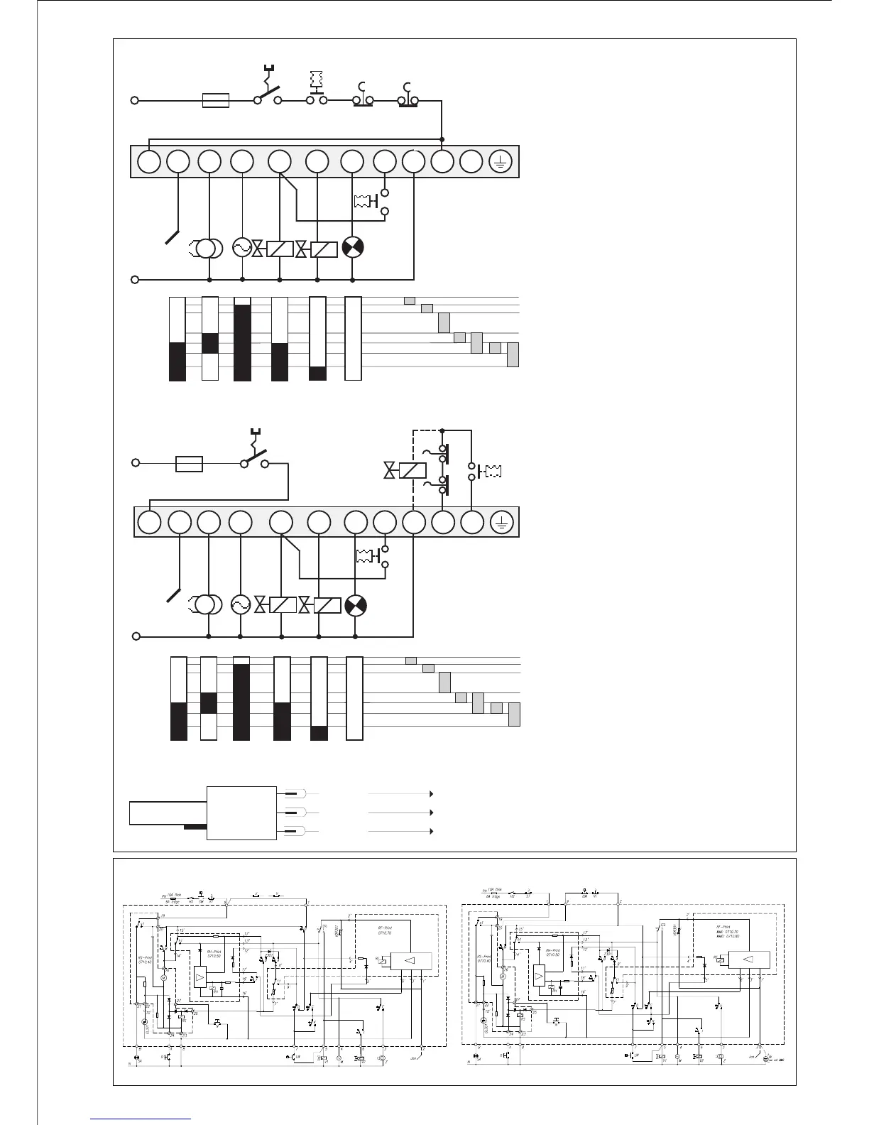
IRD CONNECTION
term. 8
term. 2
term. 9
IRD 1020
MMI 810.1 / 811.1
1 2 A/3 4 5 6 B 7 8 9 C
N
IS Z M V1 V2
SA
LW
HS
RT
ST
GW
max. 10 A rapid
6 A slow
Ph
tw tlw tv1 tvz tz ts tv2
1 2 A/3 4 5 6 B 7 8 9 C
max. 10 A rapid
6 A slow
Ph
HS
GW
ST
RT
SV
N
IS Z
MV1V2
SA
LW
tw tlw tv1 tvz tz ts tv2
SCHEMATIC CONNECTION DIAGRAM AND PROCESS DIAGRAM MMI 810.1
SCHEMATIC CONNECTION DIAGRAM AND PROCESS DIAGRAM MMI 811.1
SCHEMATIC DIAGRAM MMI 810.1 SCHEMATIC DIAGRAM MMI 811.1
HS Main switch
GW Gas pressure switch
ST Limit thermostat
RT Control thermostat
IS Ionization probe
Z Ignition
M Burner motor
V1 Solenoid valve 1st stage
V2 Solenoid valve 2nd stage
LW Air pressure monitor
SA External fault indication
SV Safety valve
tw Waiting time at start-up
tlw Max. reaction time
for air proving switch
tv1 Pre-purge time
tvz Pre-ignition time
tz Total ignition time
ts Safety time
tv2 Time delay term.6 / term.C
blue
black
brown