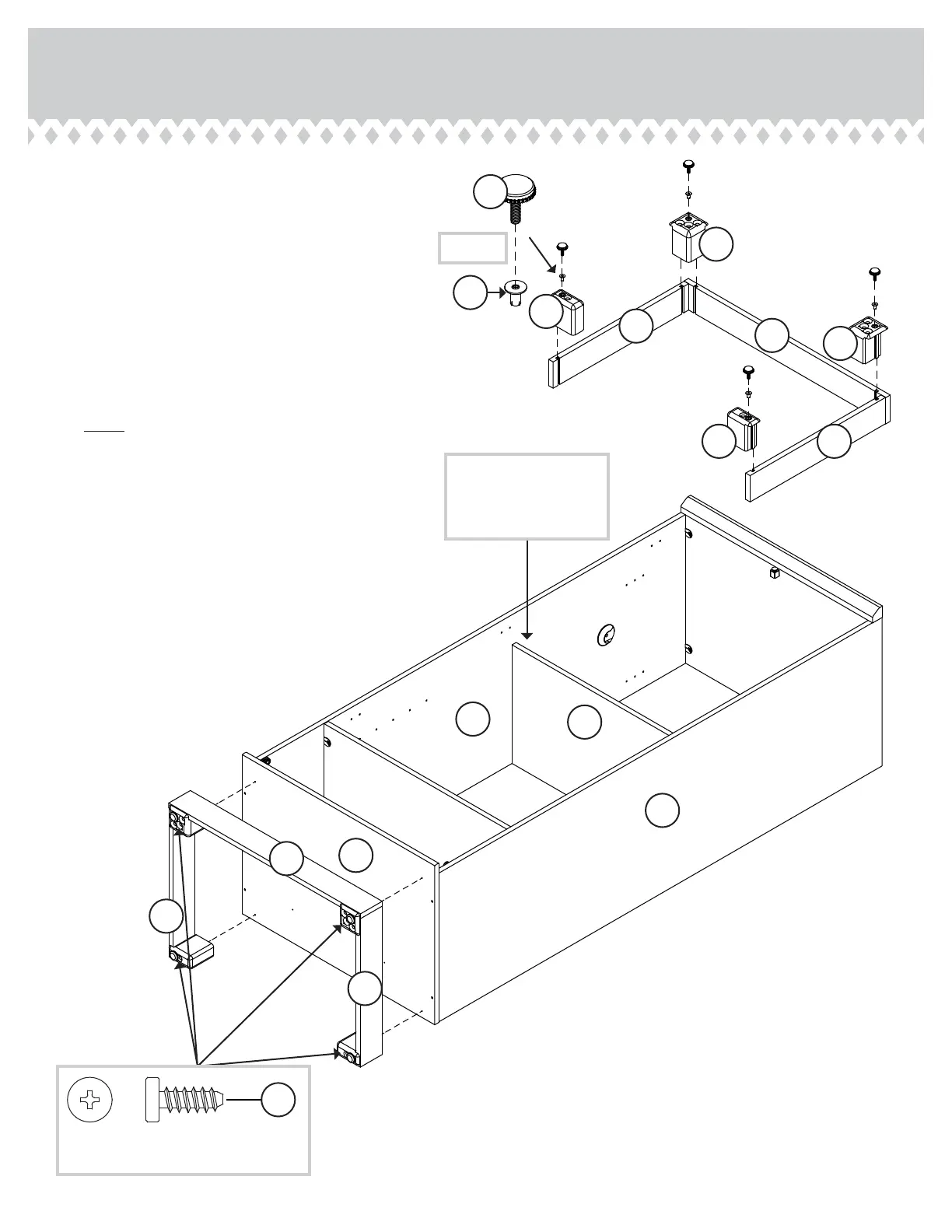
Step Step 6
å
Slide the FEET (31E and 32E) into the notches in
the SKIRTS (J and K).
å
Use a hammer to drive a PROPEL NUT (14M) into
the holes in the FEET (31E and 32E). Now, turn an
ADJUSTABLE GLIDE (18E) into each PROPEL
NUT as shown in the upper diagram.
å
Fasten the SKIRTS (J and K) to the BOTTOM (D2).
Use four BLACK 9/16" WAFER HEAD
SCREWS (33S) through the FEET and into the
BOTTOM as shown in the lower diagram.
å
NOTE: To raise a corner of the unit, turn the
ADJUSTABLE GLIDE counter-clockwise. To lower
a corner, turn the ADJUSTABLE GLIDE clockwise.
Page 11
D2
J
K
K
J
K
K
18E
14M
31E
31E
32E
32E
Insert the ADJUSTABLE
SHELF (I) between the
ENDS (A and B) before
turning over the unit.
I
A
B
BLACK 9/16" WAFER HEAD SCREW
(4 used in this step)
33S
(4 used)