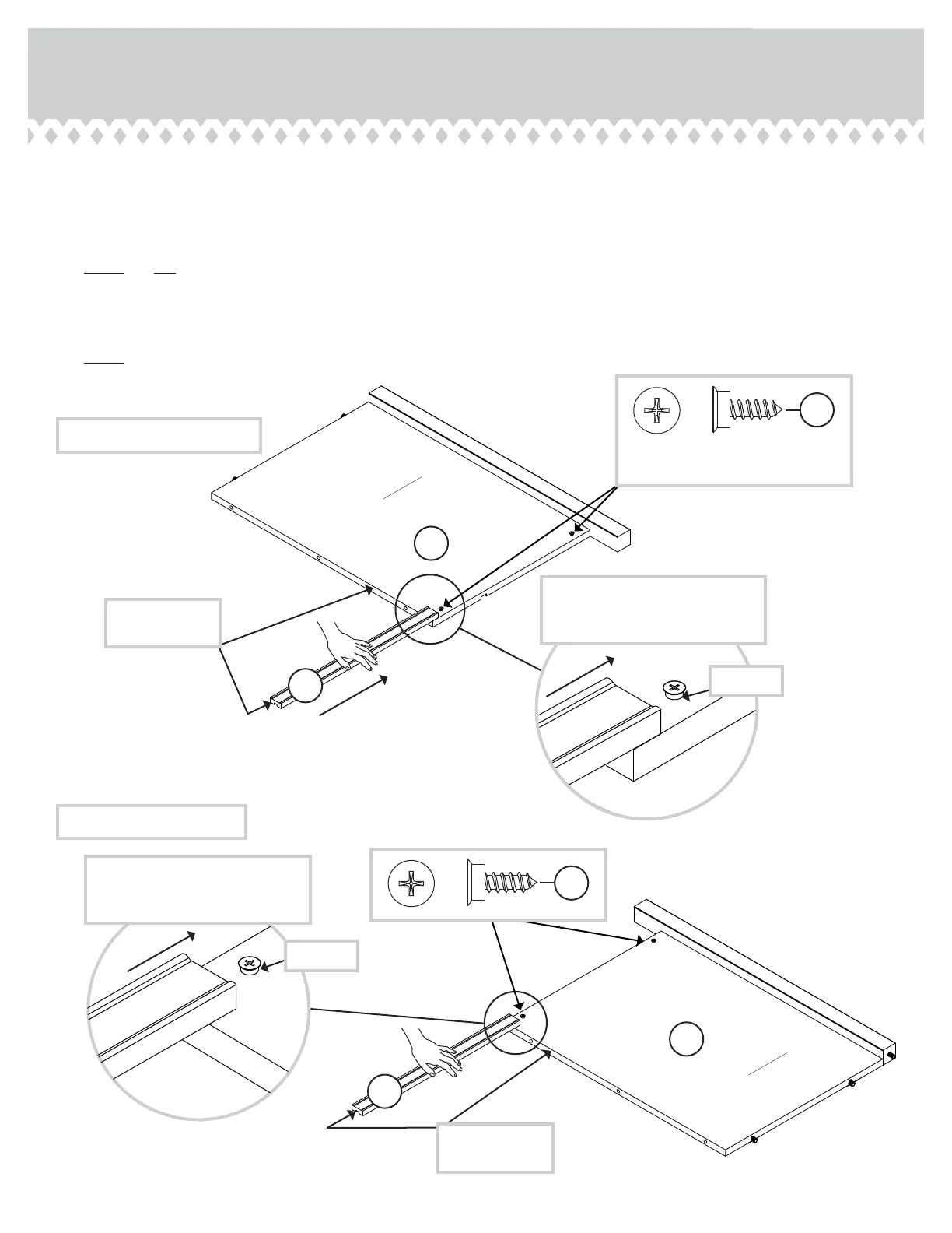
Step 5
These edes
should be even.
These edes
should be even.
Apply pressure with your hands
as you uide the MOLDINGS over
the SCREWS and onto the ENDS.
Apply pressure with your hands
as you uide the MOLDINGS over
the SCREWS and onto the ENDS.
Shoulder
Shoulder
A
B
C
C
å
Lay the ENDS (A and B) fl at on the fl oor with the HIDDEN CAM surfaces down.
å
Turn four BLACK 9/16" FLAT HEAD SCREWS (32S) into the ENDS (A and B) until the shoulders of the SCREWS rest on
the surfaces of the ENDS.
å
NOTE: Do not overtihten the SCREWS.
å
Slide the MOLDINGS (C) onto the ENDS (A and B). Line up the rooves in the MOLDINGS over the heads of the SCREWS
in the ENDS.
å
NOTE: If the MOLDING comes up o of the SCREWS, remove it and slide it on aain.
BLACK 9/16" FLAT HEAD SCREW
(4 used in this step)
32S
32S
LEFT END ASSEMBLY
RIGHT END ASSEMBLY
Surface without
HIDDEN CAMS
Surface without
HIDDEN CAMS
420040www.sauder.com/services
Pae 9