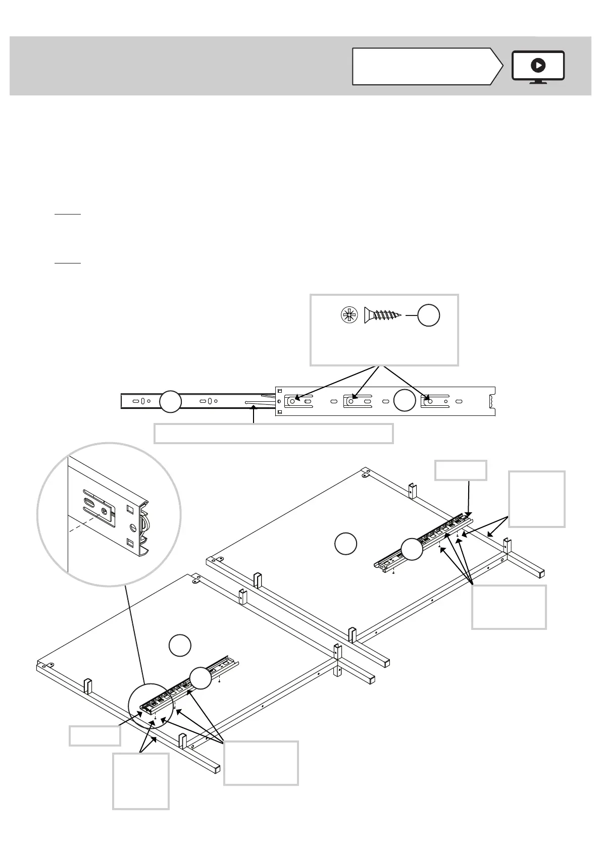
Step 1
Look for this icon. It means a
video assembly tip is available at
www.sauder.com/service/tips
å
Assemble your unit on a carpeted fl oor or on the empty carton to avoid scratching your unit or the fl oor.
å
Separate the EXTENSION SLIDES (2) from the EXTENSION RAILS (1) as shown in the upper diagram below. Be
prepared, the parts are greasy.
å
Fasten the EXTENSION RAILS (1) to the RIGHT UPRIGHT (C) and RIGHT END (D). Use six BLACK 1/2" FLAT HEAD
SCREWS (16).
å
NOTE: For each EXTENSION RAIL, turn three screws into the holes shown in the upper diagram. Slide the inner
cartridge of the EXTENSION RAIL in to fi nd the other holes that lines up with the hole in the END. Turn a SCREW into
these holes.
å
NOTE: The EXTENSION SLIDES will be used later for the DRAWERS.
C
D
2
1
1
1
Open end
Open end
Push the black lever up and pull the SLIDE from the RAIL.
BLACK 1/2" FLAT HEAD SCREW
(6 used in this step)
16
Page 5www.sauder.com/service423720
Slide the inner
cartridge to fi nd
these holes.
Slide the inner
cartridge to fi nd
these holes.
Surface with holes
Surface with holes
This hole
must be
closer to
this edge.
This hole
must be
closer to
this edge.