å
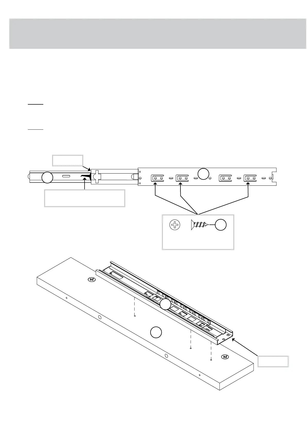
Separate the EXTENSION SLIDES (2) from the EXTENSION RAILS (1) as shown in the upper
diagram below. Be prepared, the parts are greasy.
å
Fasten an EXTENSION RAIL (1) to the UPRIGHT (G). Use three 1/2" FLAT HEAD SCREWS (16).
å
NOTE: For each EXTENSION RAIL, turn a SCREW into the 1st hole shown in the diagram.
Then, slide the inner cartridge of the EXTENSION RAIL in to nd the other holes that line
up with the holes in the UPRIGHT. Turn a SCREW into each hole.
å
NOTE: The EXTENSION SLIDES will be used later for the DRAWERS.
G
Open end
1
1/2" FLAT HEAD SCREW
(3 used in this step)
16
1
2
Open end
Push the black lever and pull
the SLIDE from the RAIL.
1
st
Surface with HIDDEN CAMS
1
st
429610whiskersupport.com Page 11
STEP 6
 Loading...