51.362/1
Sauter Components
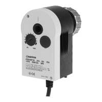
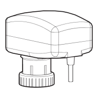
AVM 104S…115S: Valve drive with Sauter Universal Technology SUT
For controllers with continuous output (0...10V) or switched output (2- or 3-point control). To operate
through valves or three-way valves in series VXN/BXN, VUD/BUD, VUE/BUE. Choice of characteristic
(linear/equal-percentage) can be set on the actuator.
Two-part housing of fire-retardant plastic, lower part in black, upper part in yellow. With stepping motor,
SUT electronic control unit and maintenance-free gears. Fixing bracket of plastic and cap nut of brass
for fitting the valve. Assembly with the valve is practically automatic. Direction of operation can be
changed at the cable. Electronic, torque-based cut-out via stops on either the actuator or the valve;
automatic adaptation to the valve’s stroke. Coding switches for selecting characteristic and running
time. Disengageable gears for positioning the valve by hand (Allen key enclosed with product). Power
cable 1,2 m long, 5× 0,5 mm². Fitting position: anywhere from vertical to horizontal, but not upside down.
Y07552
M
100 %
0 V Output signal y 10 V
B07650
0 %
D
ir
ecti
on
of
o
pe
r
a
tio
n
2
Dire
ct
ion
o
f o
p
er
a
tio
n
1
Type Running time
s
Stroke
5)
mm
Pushing force
N
Power Weight
kg
For valves with linear characteristic, can be switched over to equal-percentage
AVM 104S F132
35/65/130 7,5 250 24 V~/=
2)
0,7
AVM 114S F132
60/120 7,5 500 24 V~/=
2)
0,7
For valves with equal-percentage characteristic, can be switched over to linear
AVM 105S F132
35/60/120 8,0 250 24 V~/= 0,7
AVM 115S F132
60/120 8,0 500 24 V~/= 0,7
Positioner
1)
Control signal 0...10V, R
i
> 100 kΩ Starting point U
0
0 or 10V
Positional feedback signal 0...10V, load > 10 kΩ Control span ΔU 10V
Switching range Xsh 200 mV
Power supply 24V∼± 20%, 50...60 Hz Protection (horizontal) IP 54 as per EN 60529
24V=
2)
+ 20% / - 10% Protection class III as per IEC 60730
Power consumption
AVM 105S F132 4,8 W 8,5 VA Response time
1)
200 ms
AVM 115S F132 4,9 W 8,7 VA
Wiring diagram A09673
Max. media temperature 100 °C Dimension drawing M09743
Permissible amb. temp. –10...55 °C Fitting instructions 1 . 4S MV 505790
Ambient humidity 5…95 %rh Fitting instructions 1 . 5S MV 506065
without condensation Declaration on materials MD 51.362
For control valve type KTM512 / TA-Regulator DN 15…50
Type Running time
s
Stroke
mm
Pushing force
N
Power Weight
kg
AVM 115S F901
80/160 10,0 500 24 V~ 0,7
Deviation from standard type: inverse scale therefore inverse direction of operation. Adaptor for
control valve available on the valve or from TA-Regulator, stating reference no. 52 757 003.
Accessories
0313529 001* Split-range unit for setting sequences; to be fitted in separate distribution box as
per MV 505671
0372145 001* Single auxiliary change-over contacts
3)
; MV 505795
0372145 002* Double auxiliary change-over contacts
3)
; MV 505795
0372249 001* Intermediate piece required for media temperature >100 °C
(recommended for temperature < 10 °C); MV 505932
0372273 001* Adaptor for Siemens VVG / VXG 44 and 48 valves; MV 505848
0372286 001 Potentiometer
4)
130 Ω; MV 505795
0372286 002 Potentiometer
4)
1000 Ω; MV 505795
0372286 003 Potentiometer
4)
5000 Ω; MV 505795
0372462 001 CASE Drives PC Tool for configuration of actuators per computer; MV 506101
*) Dimension drawing or wiring diagram are available under the same number
1) Also for 2-point or 3-point. depending on type of connection
2) 24V = for input signal of 0...10V only on AVM 1 . 4; on AVM 1 . 5S for all functions.
3) Fully variable from 0...100%; max. loading 5 (2) A. 24....230V
4) Only one potentiometer or one set of auxiliary contacts can be fitted to each drive!
5) Maximum stroke of drive = 10,0 mm
7151362003 03