Do you have a question about the sauter FL series and is the answer not in the manual?
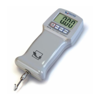
Welcomes the user and highlights the benefits of the SAUTER FL series instrument.
Instructions to check the unit for any physical damage after receiving it.
Briefly explains common features and accessing configuration via the menu key.
Details the battery supply levels and the 'battery empty' warning message.
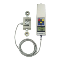
Describes how to couple fittings to the load cell stem or use an extension rod.
Explains using the M3 thread holes for mounting the gauge to a SAUTER test stand.
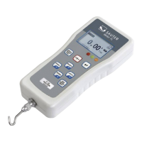
Details the process of powering up the gauge using the ON/OFF key.
Explains how the force gauge displays tensile and compressive forces with symbols.
Describes the indicator bar that shows applied load, its direction for tension/compression.
Instructions on how to zero the display, for example, to tare off grip weight.
Details the procedure to turn the display by 180° using specific button combinations.
Explains how to select different units of measurement like Newton, kgf, etc.
Describes how to switch between measurement modes like Track, Peak-Tension, Peak-Compression.
Enables the gauge to show forces applied in both directions as a live display.
Displays the maximum tensile force recorded during a measurement session.
Displays the maximum compressive force recorded during a measurement session.
Clears maximum registers and prepares for detecting the next maximum readings.
Explains how the backlight is activated by key presses or applied forces.
Details how to save readings to memory using the MEM/ENTER key.
Explains controlling the force gauge by sending RS-232 commands.
Lists commands for controlling the force gauge, such as changing mode or zeroing.
Explains how to transmit readings to a PC via the PRINT key or PC commands.
Details specific RS-232 commands for sending readings, peak values, and gauge information.
Explains how to navigate through the gauge's main menu system.
How to enter the main menu using the MENU/ESC key and navigate options.
Explains the auto-off function to conserve battery power by automatically shutting down.
Sets defined maximum and minimum forces for measuring, showing PASS or FAIL.
Used to view, delete, or print saved records from the gauge's memory.
Details the procedure for adjusting the instrument, requiring a password and weights.
Checks the load cell status, overload count, and offset percentages.
Allows selection of the output port between USB or PS/2.
Provides guidelines for best measurement accuracy and avoiding bending loads.
Lists accuracy, operating temperature, and temperature shift specifications.
Details RS-232 and USB parameters like baud rate, data bits, and sampling rate.
Diagram and description of the RS 232 connector pinout and interface.
Guide for performing the calibration procedure with password entry.
Describes the calibration procedure, requiring a password and proper masses.
Ensures the instrument is acclimatized to the calibration laboratory temperature for at least two hours.
Involves fitting charged batteries or connecting a power supply before calibration.
Steps for entering the password, accessing the calibration menu, and setting max capacity.
Procedure to set tension zero and maximum gain for accurate tension measurements.
Procedure to set compression zero and maximum gain for accurate compression measurements.
Steps to store original offset, date, time, and clear overload counter after calibration.
| Brand | sauter |
|---|---|
| Model | FL series |
| Category | Measuring Instruments |
| Language | English |