Multi-Gang Installations
When combining multiple Switches, Dimmers, Auxiliary Controls, Keypads, and Fan Controllers into a multi-ganged box, the tabs on
the inside need to be removed to be able to fit all devices into the electrical box. Below are examples of 4, 3, and 2-gang scenarios.
•
Tabs are removed from both sides of inside gang devices.
•
Tabs are NOT removed from outside edges of the devices at the end of each gang.
Electrician Removal/Installation Instructions
To ensure proper installation, a qualified electrician should do the following.
ELECTRIC SHOCK: The 120V AC, 60 Hz source power poses an electric shock hazard that has the potential to cause serious injury to
installers and end users.
IMPORTANT:
•
A licensed electrician is required to install any Savant wireless switches. Isolate and turn off the power at the main breaker panel prior
to replacing any electrical devices.
•
For line, load, neutral, and ground connections, use only #14 AWG or larger solid copper wires (80°C) with insulation stripped to
⅝” (16 mm).
1. At the main breaker panel, switch the breaker that supplies power to the switch being replaced to Off.
2. Unscrew the wall plate and remove. Verify power is removed using a 120V AC tester.
3. Unscrew the two 6-32 flat head screws and remove the existing toggle/rocker switch.
4. Disconnect the in-wall wires from the existing device and remove the device. It is good practice to label each wire as it is
removed. If not already identified, mark wires to ensure proper installation. Especially if the circuit employs a 3-way
configuration.
5. Connect the in-wall wires to the leads coming from the Metropolitan wireless switch using the supplied wire nuts or approved
alternative. Refer to the Wiring Diagrams and Rear View Descriptions sections.
6. Insert the switch into the electrical switch box and secure with the 6-32 flat head screws provided. DO NOT use a powered
screw driver. A powered screw driver can over tighten the screws.
7. Re-establish power at the main breaker panel.
8. Press the reset button on the front panel with the load attached. This calibrates the switch to the circuit it is being installed to.
9. Once the switch has calibrated itself to the load, the switch will go into a quick diagnostic and the LEDs will cycle as follows:
•
All LEDs will illuminate bright and then flash twice.
•
Next, the two LEDs on the main button will flash several times in sync.
•
From there, the same two LEDs on the main button will blink. Refer to the LED Sequencing table.
LED Sequencing
LEDs blink in an
alternating pattern
The switch is in AP Mode and waiting to be provisioned through either the Web UI or
SmartConnect. After approximately 60 seconds, the blinking will stop. In this scenario, the switch
is still in AP Mode. The blinking was stopped intentionally for cases where the switch is not put
on the network immediately and can be used as a manual switch till provisioned.
1st LED illuminates solid.
2nd LED blinks.
The switch is connected to the local network (IP Address assigned) but not bound to the host/
controller. The blinking will stop after 60 seconds but the switch will remain in this state.
The switch was previously provisioned and is trying to establish a connection with the local
network but the settings are incorrect. The switch will need to be reset to its default values and
reconnected with the correct network settings. The blinking will stop after 60 seconds but the
switch will remain in this state.
Note: Pressing any button on the front panel after cycling has stopped will begin a new cycle period with only a 20 second duration.
10. To test without connecting to a local network, press the switch button to the On (up) position and observe the load switches
on. Press the switch button to the Off (down) position and observe the load switches Off.
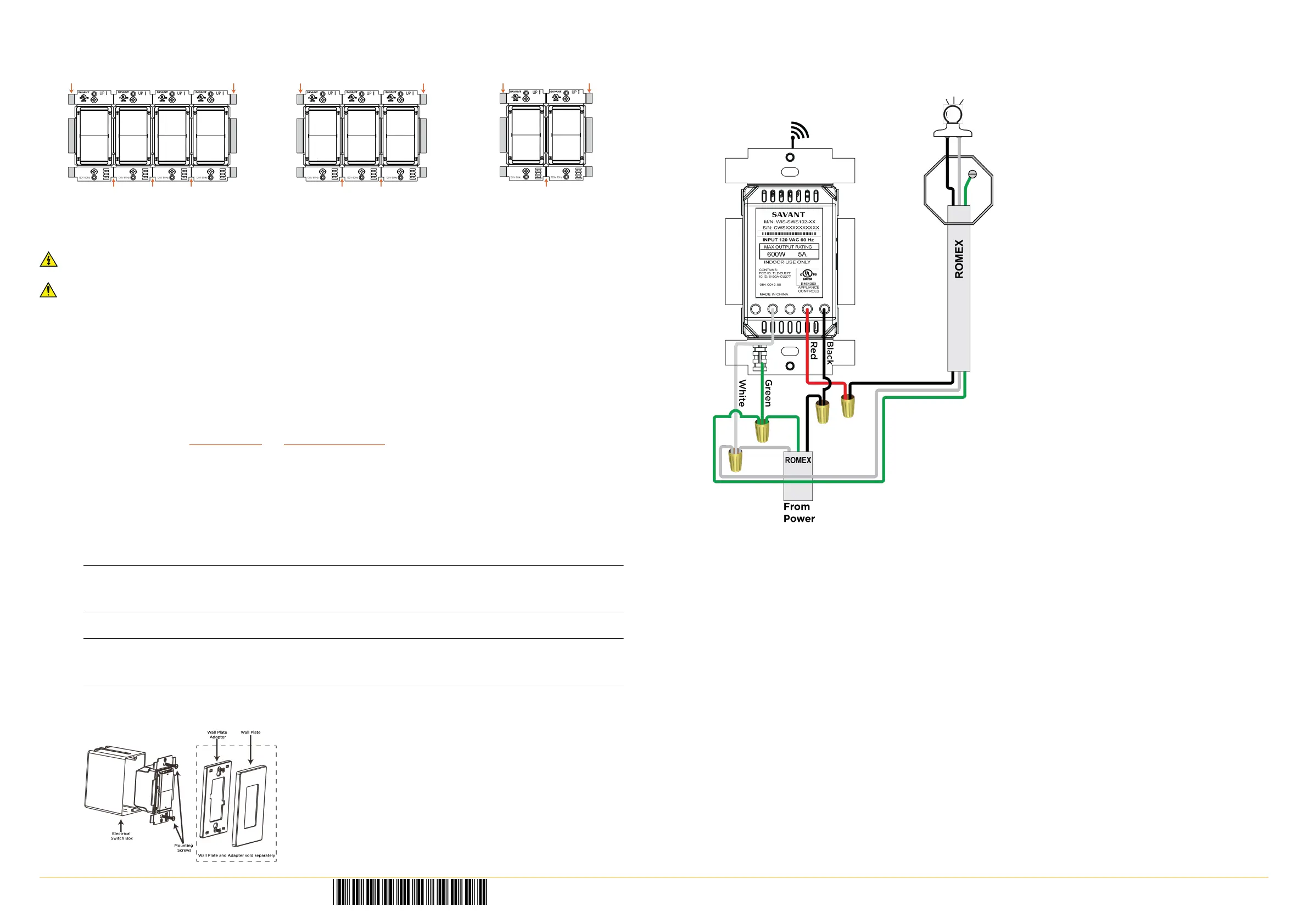
Wiring Diagrams
The diagrams below display how to wire the Metropolitan Switch. Any unused wires must have the bare wire portion (stripped end)
cut off and the wire must be capped with a wire nut.
Single Switch Installation Example
When ready to connect to a local network, refer to the Metropolitan Wireless Lighting Deployment Guide (009-1342-00).
Regulatory
The following statements are applicable to the Metropolitan Wireless Dimmers, Switches, Keypads, and Fan Controllers.
FCC Regulations:
15.19. These devices comply with part 15 of the FCC Rules. Operation is subject to the following two conditions: (1) These devices may
not cause harmful interference, and (2) these devices must accept any interference received, including interferences that may cause
undesired operation.
15.21. The changes or modifications not expressly approved by the party responsible for compliance could void the user's authority to
operate the equipment.
15.105. This equipment has been tested and found to comply with the limits for CLASS B digital device, pursuant to Part 15 of FCC
Rules. These limits are designed to provide reasonable protection against harmful interference when the equipment is operated in a
residential environment. This equipment generates, uses and can radiate radio frequency energy and, if not installed and used in
accordance with the instructions, may cause harmful interference to radio communications, However there is no guarantee that
interference will not occur in a particular installation, If this equipment does cause harmful interference to radio or television
reception, which can be determined by turning the equipment off and on, the user is encouraged to try to correct the interference by
one or more of the following measures:
- Reorient or relocate the receiving circuit different from that to which receiver is connected.
- Increase the separation between the equipment and the receiver.
- Consult the dealer or experienced radio/TV technician for help.
IC Regulations:
RSS-Gen 7.1.3. These devices comply with Industry Canada license-exempt RSS standard(s). Operation is subject to the following two
conditions: (1) These devices may not cause interference, and (2) These devices must accept any interference, including interference
that may cause undesired operation of the device.
RSS-21- Annexe 9: A 9.4. Le présent appareil est conforme aux CNR d'Industrie Canada applicables aux appareils radio exempts de
licence. L'exploitation est autorisée aux deux conditions suivantes: (1) l'appareil ne doit pas produire de brouillage, et (2) l'utilisateur
de l'appareil doit accepter tout brouillage radioélectrique subi, même si le brouillage est susceptible d'en compromettre le
fonctionnement.
Metropolitan Wireless Switch | 009-1337-01 | 150522
45 Perseverance Way, Hyannis, MA 02601
Copyright © 2015 Savant Systems, LLC
Savant.com | 508.683.2500
 Loading...