PAV-SIPA50SM / PAV-SIPA50SMV2 Quick Reference Guide | 009-1658-03
Copyright 2021 Savant Systems Inc. | 210719
45 Perseverance Way, Hyannis, MA 02601
Savant.com | 508.683.2500
2 of 3
Expansion
Up to sixteen Savant IP Audio devices can be connected in a single
system, providing a virtual audio switch that can be configured to suit
almost any need.
Network Requirements
For information on network requirements, refer to the Savant Device
Networking Guidelines on the Savant Community.
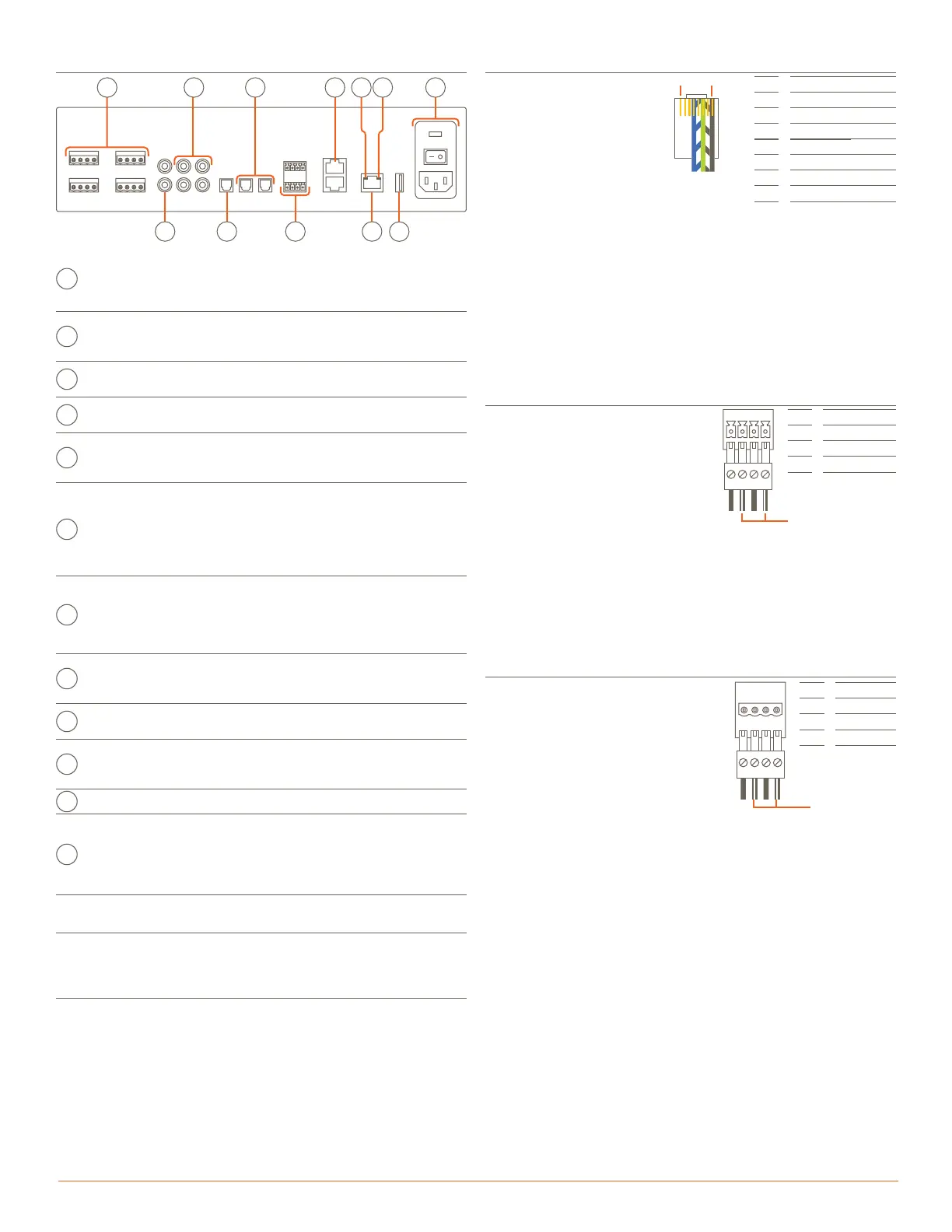
Speaker Connections
-
R +
-
L +
Zone 1
432
1
Pin 1
Pin 2
Pin 3
Pin 4
Right -
Right +
Left -
Left +
Use white stripe
for positive (+)
Speaker wiring connections are made
using 4-pin Speaker Connectors
supplied with the device. The wire slips
into the hole and locks with a screw
located at the top of the connector.
Speaker connectors accept up to
12AWG speaker cable.
NOTES:
– Wire order shown does not represent any wiring standard. It may
be dierent than other models.
– While not shown in the diagram above, Zones 2 to 4 follow the
same wiring as Zone 1.
RS-232 Connections
Pins 7 and 8 are only required
for CTS/RTS handshaking.
Pin 1
Pin 2
Pin 3
Pin 4
Pin 5
Pin 6
Pin 7
Pin 8
No Connection
No Connection
No Connection
Ground (GND)
Receive (RXD)
Transmit (TXD)
Clear to Send (CTS)
Request to Send (RTS)
Pin 1 Pin 8
RJ-45 Connector
(Gold pins face up)
IMPORTANT: When wiring to
this port, do not connect any
wires within the cable that are
not required for
communication.
NOTES:
– CTS/RTS handshaking is supported for flow control based on the
profile used in the configuration.
– Wire coloring is included to identify the pins used for this
connection. Colors shown do not represent any wiring standard.
– The IP Audio 125 does not support RS-422/485.
RJ-45 to DB9 Adapter: Savant oers RJ-45 to DB9 adapters in a
variety of configurations that can be used for RS-232 control.
Refer to the RS-232 Conversion to DB9 and Pinout Application Note
located on the Savant Customer Community for more information on
RJ-45 to DB9 adapters.
Rear Panel
G
F
E
D
C
B
A
L
K
JI
H
Speaker
Connections
(4) Speaker output zones
Uses 4-pin Speaker Connectors.
NOTE: Compatible with 8 ohm or
4 ohm speakers.
B
Analog
Preamp
Output
(1) Analog stereo line output (Left & Right)
Direct Line Level 2.1-V
RMS
Output.
C
Analog Input
(2) Analog stereo inputs (Left & Right)
RCA line-level inputs; 22 kΩ input impedance.
D
Digital Audio
Out
(1) Digital optical preamp output (TOSLINK), line-
level 96kHz/24-bit output, fixed volume.
E
Digital Audio
In
(2) Digital optical audio inputs (TOSLINK)
Supports up to 96kHz/24-bit digital audio in;
PCM stereo format only.
F
IR
(4) IR Ports
Uses 4-pin IR Connectors to send IR signals to
control devices with an IR input or IR receiver via
an IR flasher (5V tolerant only). See the IR Wiring
section for important precautions regarding IR
functionality before making any connections.
G
RS-232
8-pin RJ-45 port used to transmit and receive
serial binary data to and from serial controllable
devices. CTS/RTS handshaking availability
based on component profile. See the RS-232
Connections section for pin-outs.
H
Ethernet
8-pin RJ-45 port
100 Base-T auto-negotiating port.
Supports Audio Video Bridging (AVB).
I
Ethernet
Activity LED
Green Blinking: Activity (Rx/Tx)
O: No Activity
J
Ethernet
Link LED
Green Solid: Ethernet Link is established (any
speed).
O: Ethernet link is not established.
K
USB USB 2.0 Type A (reserved for future use)
L
Power Input
100/240V AC (50/60 Hz) 3.6A
Fuse: 250V 3.0A slow blow fuse; field replaceable
I/O (power switch):
I (On): Powers On the chassis.
O (O): Powers O the chassis.
IR Wiring
Pin 1
Pin 2
Pin 3
Pin 4
IR 1 -
IR 1 +
IR 2 -
IR 2 +
Use white stripe
for positive (+)
IR connections are made using
4-pin IR Connectors supplied with
the device. The wire slips into the
hole and locks with a screw
located at the top of the
connector.
IMPORTANT: IR Wiring Precautions
Ensure that all IR emitters are within 15 feet (4.6 meters) from the
controller’s location.
Use of 3rd party blinking IR emitters with Talk Back is not
recommended. These types of emitters can draw voltage away from
the IR signal that can degrade IR performance.
NOTE: While not shown in the diagram above, IR connections 3 to 4
follow the same wiring as 1 to 2.
432
1
-
1 +
-
2 +
 Loading...