SHR-S2-xx Quick Reference Guide | 009-1907-05
Copyright 2021 Savant Systems, Inc | 211201
45 Perseverance Way, Hyannis, MA 02601
Savant.com | 508.683.2500
2 of 2
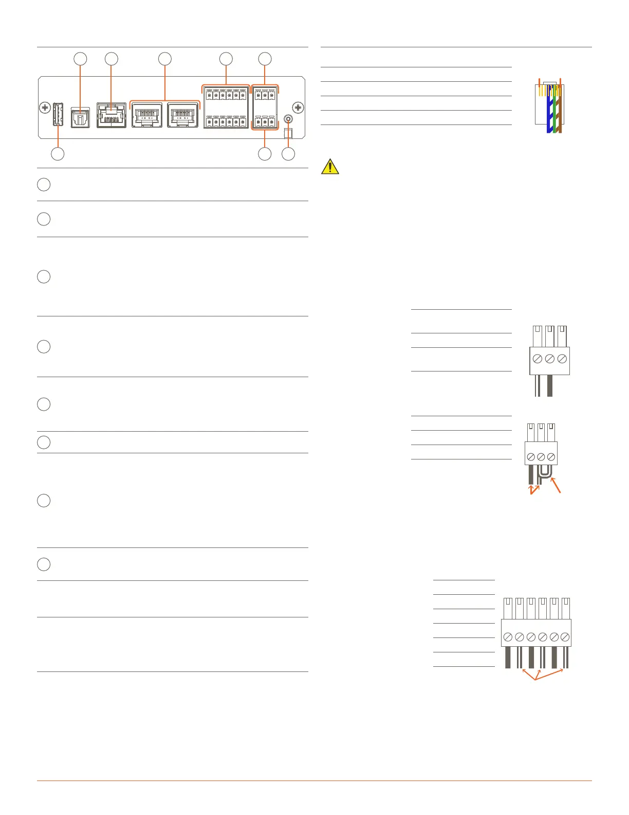
Control Connections
RS-232 Wiring
Pin 1: No Connection Pin 5: RXD (Receive)
RJ-45 Connector
(Gold pins facing up)
Pin 1 Pin 8
Pin 2: No Connection Pin 6: TXD (Transmit)
Pin 3: No Connection Pin 7: CTS (Flow Control)
Pin 4: GND (Ground) Pin 8: RTS (Flow Control)
IMPORTANT!
– Wire colors are included to identify the pins used for this
connection. Colors shown do not represent any wiring standard.
– DO NOT connect any wires within the cable that are not required
for communications.
– Pins 7 & 8 are only required for CTS/RTS handshaking.
– CTS/RTS handshaking is supported for flow control based on the
profile used in the Blueprint configuration.
– RS-422/485 is not supported
– Refer to the RS-232 Conversion to DB-9 and RS-422/485 Pinout
Reference Guide on the Savant Customer Community for more
information on RJ-45 to DB9 adapters oered by Savant.
Relay Wiring
Both Normally Open
and Normally Closed
outputs are available.
Pin 1: NC
(Normally Closed)
Pin 2: Common
Pin 3: NO
(Normally Open)
GPIO - General Purpose Input/Output
– GPIO’s configured
as an output can
be used to trigger
an action within
the system such as
switching a device.
– GPIO configured
as an input can
detect a state
change and trigger
a workflow.
Pin 1: GND (Ground)
32
1
GPIO 1
Standard
GPIO Using
PD Jumper
Gnd
I/O
PD
Pin 2: GPIO 1
Pin 3: PD (Pulldown)
– GPIO pins configured as an input are pulled high to (+12V) during
the boot process. To force the GPIO signal low during a boot-up.
Connect the PD pin to the GPIO pin. This forces the GPIO output to
(< 0.8V) during the processor boot times.
IR Wiring (Infrared)
– Ensure that the all IP
emitters are within 15
feet (4.6 meters) from
the controller’s location.
– Use of 3rd party
flashing IR emitters
with Talk Back is not
recommended. These
types of emitters can
draw voltage away from
the IR signal that can
degrade IR performance.
Pin 1: IR 1 -
1
+-
+-
+-
2
3
4 5 6
Use White Stripe
for Positive (+)
Pin 2: IR 1 +
Pin 3: IR 2 -
Pin 4: IR 2 +
Pin 5: IR 3 -
Pin 6: IR 3 +
– IR connections IR4 to IR6 (not shown in diagram) follow the same
wiring as connections IR1 to IR3.
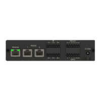
Rear Panel
USB
Audio
Ethernet RS232-1 RS232-2
+
2
+
-
1
-
IR
3
-
+
C
Relay
NC NO
++
-
4
-
5
+
-
6
1
GPIO
G PD
5VDC
A B
C D E
A
Audio
Digital optical audio (TOSLink) input. Supports
up to 192kHz/24-bit digital audio in; PCM stereo
format only.
Ethernet
8-pin RJ-45 female.
100 Base-T auto negotiating port. Connecting to
this port will disable Wi-Fi settings.
RS-232
8-pin RJ-45 female.
Used to transmit and receive serial binary data to
and from serial controllable devices.
Ports 1-2 RS-232 - CTS/RTS handshaking. CTS
RTS handshaking availability is based on the
component profile.
See the RS-232 Wiring section for pin-outs.
IR
6-pin Screw Down Plug-in Connector. Used to
send IR signals to control devices with an IR
input or IR receiver via an IR flasher (5V tolerant
only). See the IR Wiring section for important
precautions regarding IR functionality before
making connections.
Relay
3-pin Screw Down Plug-in Connector. See the
Relay Wiring section for pin-outs.
Normally Open (NO) / Normally Closed (NC) to
control devices requiring basic on/o operation.
DC Voltage Max: 30V DC 1A
USB Not Used
G
GPIO
3-pin Screw Down Plug-in Connector. See the
GPIO Wiring section for pin-outs.
GPIO Input - When configured as an input, the
processor will look for a low (<0.8V DC) or a high
(>2.4V DC) state. Minimum 0V DC / Maximum
12V DC.
GPIO Output - When configured as an output,
the port provides a binary output of 0-12V DC
150mA max.
H
5V DC
5V DC 3A - Connect included wall wart power
supply between the 5V DC connection and a 115-
240V AC surge protected outlet.
Network Requirements
For more information, see the Savant Device Networking Guidelines on
the Savant Customer Community.
Further Product Information
To view available documentation, detailed product specs, and more:
– Visit the Savant Knowledge tab via the Savant Customer
Community to search all Savant documentation.

 Loading...