Box Contents
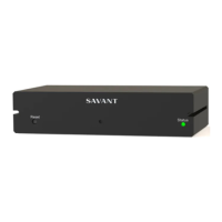
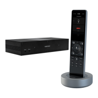
(1) Savant® Smart Host with Control 2 (SHC-S2-00)
(1) 5V DC 3A Power Supply
with 4 Quick Change AC Adapters (025-0153-xx)
(2) M3x6 mm Flathead Phillips Screw Black (039-0001-xx)
Wall Bracket:
(1) Wall Mount Frame (074-0585-xx)
(1) Host Mount (074-0584-xx)
(2) 6-pin Screw Down Plug-in Connector Black (028-0664-xx)
(2) 3-pin Screw Down Plug-in Connector Black (028-0665-xx)
(1) Quick Reference Guide (this document)
Specifications
32° to 104° F (0° to 40° C)
10% to 90% Relative Humidity (non-
condensing)
Net: 1.3 lb (0.58 kg)
Shipping: 2.1 lb (0.95 kg)
FCC Part 15 | CE | C-Tick | ICES-003
Minimum Supported Release
Minimum Supported Release
Chassis Installation
The Smart Host can be installed on a solid, flat, level surface such as
a table, cabinet, or shelf, or wall mounted using the included 2 piece
bracket. The location should be dry, well ventilated, and out of
direct sunlight. When placing the Smart Host on a shelf, the wall
bracket must not be installed to allow for a flat, level installation.
Rack Installation
The optional RCK-3000-xx provides a ventilated shelf for mounting
up to 2 Smart Hosts. When rack mounting the Smart Host, the wall
bracket must not be installed to allow for a flat, level installation.
Wall Bracket Installation
A 2 piece wall bracket is included that can be used to mount the
Smart Host to a wall or back of a cabinet.
1. Attach the host bracket to the rear of the host using the included
M3x6 mm Flathead Phillips Screws.
2. Attach the wall bracket to the wall. Screws to attach are not
included.
3. Position the host over the wall bracket and gently slide into place.
See Wall Bracket Diagram on page 2.
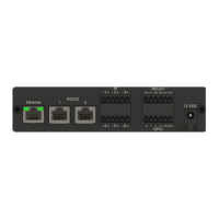
Rear Panel
Press and hold for 5 seconds while powered
On to clear wired Ethernet settings. Status
LED will blink rapidly when reset is complete.
Note: This will reset the network settings to
factory defaults. Any static IP
Addresses settings will be lost.
5V DC 3A - Connect to included power
supply.
Off: Disconnected from power supply.
Amber: Controller is booting/rebooting
and is disconnected from the network.
Amber Flashing: Smart Host is not
connected to a wired Ethernet network.
Green: Connected to wired Ethernet
Network.
TOSLink (Optical) digital audio output.
Connect to digital optical audio input on
switcher for using the Audio Interrupt Service
(AIS).
8-pin RJ-45 female.
10/100/1000 Base-T auto-negotiating port.
8-pin RJ-45 female.
Used to transmit and receive serial binary
data to and from serial controllable devices.
Ports 1-2 RS-232 - CTS/RTS handshaking.
CTS/RTS Handshaking availability based on
component profile.
See RS-232 Wiring for pinouts.
6-pin Screw Down Plug-in Connector.
Used to send IR signals to control devices
with an IR input or IR receiver via an IR flasher
(5V tolerant only). See IR Wiring for
important precautions regarding IR
functionality before making any connections.
3-pin Screw Down Plug-in Connector.
See Relay Wiring for pinouts.
Normally Open (NO) Normally Closed (NC)
to control devices requiring basic on/off
operation. DC Voltage Max: 30V DC 1A.
3-pin Screw Down Plug-in Connector.
See GPIO Wiring for pinouts.
GPIO Input: When configured as an input,
the processor will look for a low (<0.8V DC)
or a high (>2.4V DC ) state.
Minimum 0V DC / Maximum 12V DC
GPIO Output: When configured as an output,
the port provides a binary output of 0-12V
DC 150mA max.
SHC-S2-00 | 009-1565-00 | 170925
45 Perseverance Way, Hyannis, MA 02601
Copyright © 2017 Savant Systems, LLC
savant.com | 508.683.2500
Savant® S2 Host
Quick Reference Guide