Do you have a question about the SBE SB-34 and is the answer not in the manual?
Discusses the history and advantages of SSB over AM.
Visual comparison of AM and SSB power distribution.
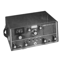
General description of the SB-34 and its design features.
Explains the function of the power ON/OFF and volume control.
Describes the dual-speed reduction drive tuning knob.
Details the microphone jack and compatible microphone types.
Explains how the bandswitch controls band selection and tuning.
Describes the pitch control for fine-tuning receiver frequency.
Explains the dial correct knob for calibration adjustments.
Details the switch for selecting upper or lower sideband.
Describes the function of the CAL switch for the calibrator unit.
Explains the XMTR switch for mobile/AC operation and power saving.
Describes the PA TUNE control for loading and sensitivity.
Details the steps for tuning the power amplifier and driver.
Explains the overall transmit and receive signal flow.
Explains the operation of the electronic keying circuit.
Describes the function and operation of the balanced modulator circuit.
Explains the operation of a typical bilateral stage.
Explains the purpose of the mechanical filter.
Details how sideband selection is achieved using switches and circuits.
Explains the VFO operation and its role in frequency translation.
Explains the HF oscillator, mixer, and RF amplifier circuits.
Describes the function of the power amplifier and neutralization.
Explains the automatic gain control circuit and its operation.
Details the DC operation of the power supply.
Details the AC operation of the power supply.
Explains the voltage regulator circuit for VFO stability.
Lists the equipment needed for troubleshooting.
Steps to perform before starting detailed troubleshooting or alignment.
Chart for diagnosing common alignment and operational problems.
Detailed procedures for aligning the transceiver's circuits.
Step-by-step procedure for aligning the transmitter section.
Chart for diagnosing alignment problems.
Table of transistor voltage readings under specific conditions.
Diagram showing component locations on the VFO board top.
Diagram showing component locations on the VFO board bottom.
Diagram showing component locations on the IF board top.
Diagram showing component locations on the IF board bottom.
Diagram showing component locations on the Tuner board top.
Diagram showing component locations on the PA Cavity top.
Diagram showing component locations on the Tuner board bottom.
Diagram showing component locations on the Crystal Oscillator board bottom.
Diagram showing component locations on the chassis top.
Diagram showing component locations on the chassis bottom.
Modification to add AC fuse protection.
Modification for capacitor replacement.
Modifications for erratic operation, intermittent issues, or power fade.
Modification for gain instability or motor boating.
Modification to prevent "Talk Back".
Specific capacitor change for chassis 23 and below.
Modification for Vernier Drive mounting bracket.
Modification to prevent power inverter interference.
Modifications to reduce frequency drift.
Modification to address receiver distortion.
| Brand | SBE |
|---|---|
| Model | SB-34 |
| Category | Transceiver |
| Language | English |