SERIAL PROTOCOL USER’S MANUAL SWEEP V1.0
8
Copyright ©2014-2017 Scanse LLC - www.scanse.io
• Initiates scanning
• Sensor responds with header containing status.
• Sensor begins sending constant stream of Data Block receipts, each containing a single sensor readings. This
stream continues indefinitely until the host sends a DX command.
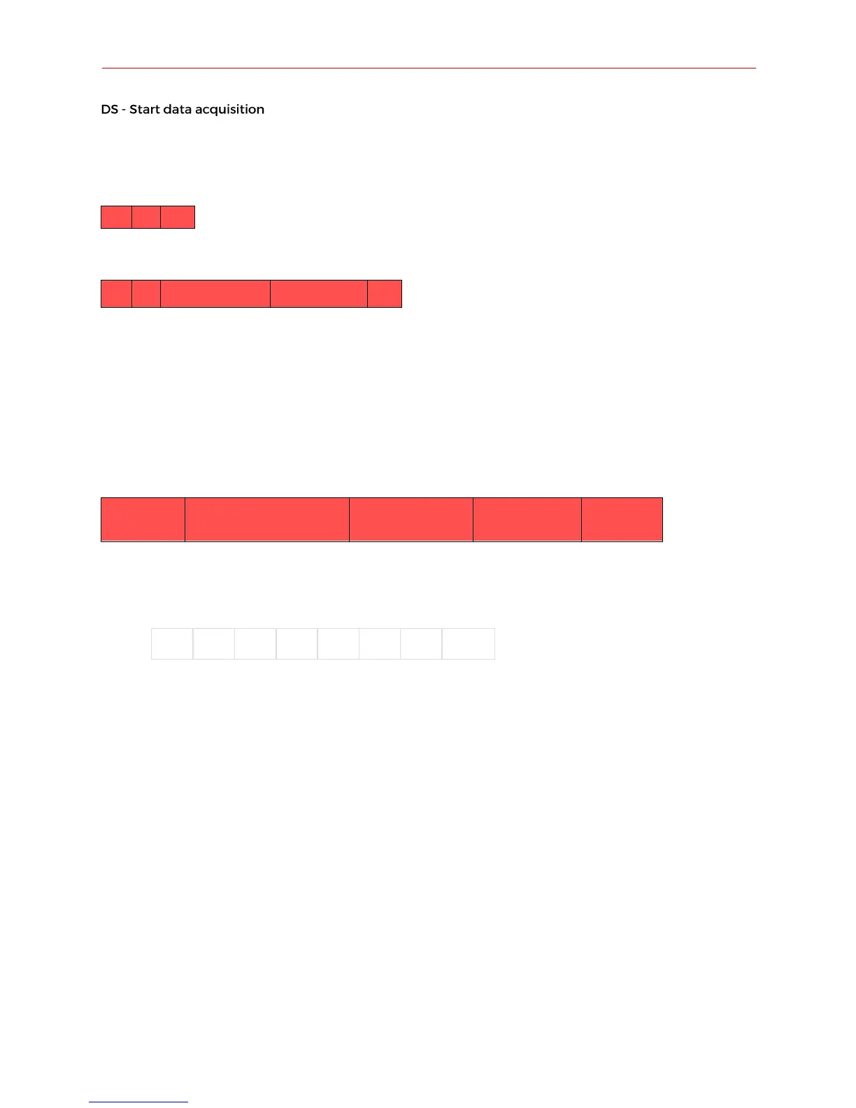
(HOST -> SENSOR)
(SENSOR -> HOST)
Header response
The DS command is not guaranteed to succeed. There are a few conditions where it will fail. In the event of a
failure, the two status bytes are used to communicate the failure.
Status Code (2 byte ASCII code):
• ‘00’: Successfully processed command. Data acquisition effectively initiated
• ‘12’: Failed to process command. Motor speed has not yet stabilized. Data acquisition NOT initiated. Wait
until motor speed has stabilized before trying again.
• ‘13’: Failed to process command. Motor is currently stationary (0Hz). Data acquisition NOT initiated.
Adjust motor speed before trying again.
(SENSOR -> HOST)
Data Block (7 bytes) Data Block
Azimuth - degrees(float)
(2 bytes)
Distance - cm(int)
(2 bytes)
Data Block Structure:
The Data Block receipt is 7 bytes long and contains all the information about a single sensor reading.
• Sync/Error Byte: The sync/error byte is multi-purpose, and encodes information about the rotation of the
Sweep sensor, as well as any error information. Consider the individuals bits:
o Sync bit: least significant bit (LSB) which carries the sync value. A value of 1 indicates that this
Data Block is the first acquired sensor reading since the sensor passed the 0 degree mark. Value
of 0 indicates all other measurement packets.
o Error bits: 7 most significant bits (e0-6) are reserved for error encoding. The bit e0 indicates a
communication error with the LiDAR module with the value 1. Bits e1:6 are reserved for future
use.
• Azimuth: Angle that ranging was recorded at (in degrees). Azimuth is a float value, transmitted as a 16 bit
int. This needs to be converted from 16bit int to float. Use instructions in the Appendix. Note: the lower
order byte is received first, higher order byte is received second.
• Distance: Distance of range measurement (in cm). Distance is a 16 bit integer value. Note: the lower order
byte is received first, higher order byte is received second. Use instructions in the Appendix.
• Signal strength : Signal strength of current ranging measurement. Larger is better. 8-bit unsigned int,
range: 0-255
• Checksum: Calculated by adding the 6 bytes of data then dividing by 255 and keeping the remainder.
(Sum of bytes 0-5) % 255 ... Use the instructions in the Appendix.