1
2
Installation instructions electronic step co n trol EMS 03-4
2
Date: 02.12.2016 8220319 MA / EN
3 Mechanical installation
Das Gerät ist für die Wandmontage mit den An-
schlüssen nach unten oder Bodenmontage vorge-
sehen.The device is designed for wall mounting
with the connections facing down or for floor
mounting.
" Install in a dry area.
" Ensure that there is a minimum clearance to
the surrounding equipment:
F Ensure that there is at least 1 cm clearance
on all sides -- except the mounting side.
F During operation the surrounding tempera-
ture should not exceed +70 C (measured at
2.5 cm clearance to the sides of the device).
" Screw the step control with two screws (screw
diameter 6 mm) in the designated drill holes.
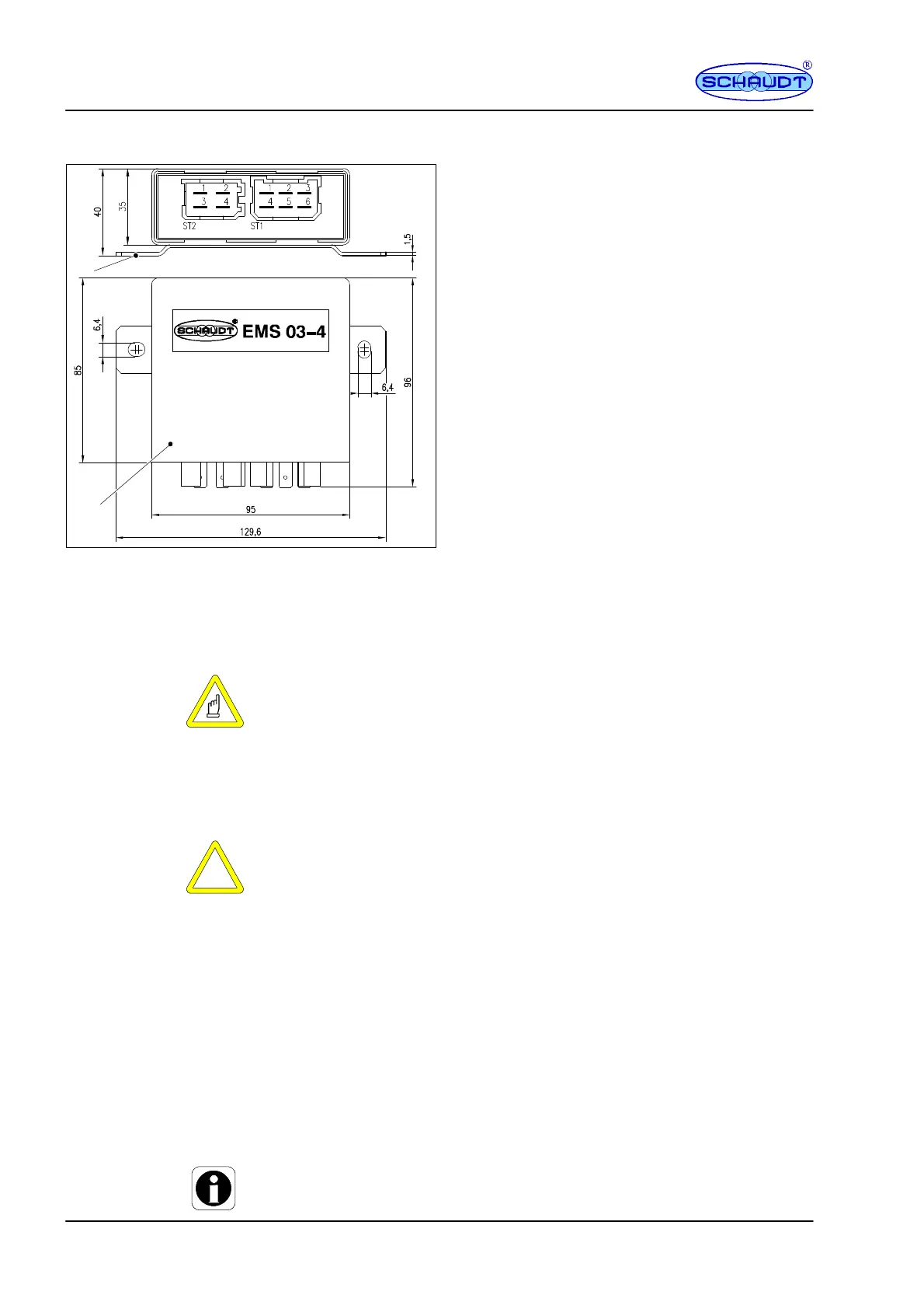
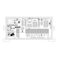
Fig. 1 Dimension illustration EMS 03-4 (measurements in mm)
1 Assembly bracket (galvanised)
2 Housing PA
4 Electrical co nnection
Y W ARNING!
Protection against reverse polarity
Damaging the electrical equipment of the basic vehicle:
F Ensure that the necessary voltage levels for the control voltages cor-
respond with the necessary values.
F Only make connections if the system is not connected to a power sup-
ply.
Y ATTENTION!
Short circuits
Damage to the step control or cable burn:
F To protect the wire transmissions, insert fuses directly at the battery
plus pole.
Select cable thickness 1 or 2 in accordance with EN 1648. The maximum
current must not exceed 90% of the safety value.
Connect the step control in the following sequence (also see the block dia-
gram:
1. All connections to the buttons
2. Motor
3. Battery voltage
Disconnect in the reverse order.
Y Individual blade receptacles AMP 6.3 can be used for the connection. Al-
ternatively, suitable wire harness can be used for ST1 and ST2.
Connection -sequence
Disconnection