Installation instructions electronic step co n trol EMS 03-4
3
Date: 02.12.2016
8220319 MA / EN
+--
Electronic
+12V (feed--in)
Motor
Motor
Negative battery
6
321
45
12
43
ST1
ST2
Drive in/lock [ST1--6] button
button
Minus for
Drive out/open [ST1--5] button
Drive out/open [ST1--2] button
Drive in/lock [ST1--3] button
[ST1--4]
[ST1--1]
Minus for
button
M
Motor control
EMS 03-4
Fuse
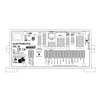
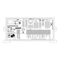
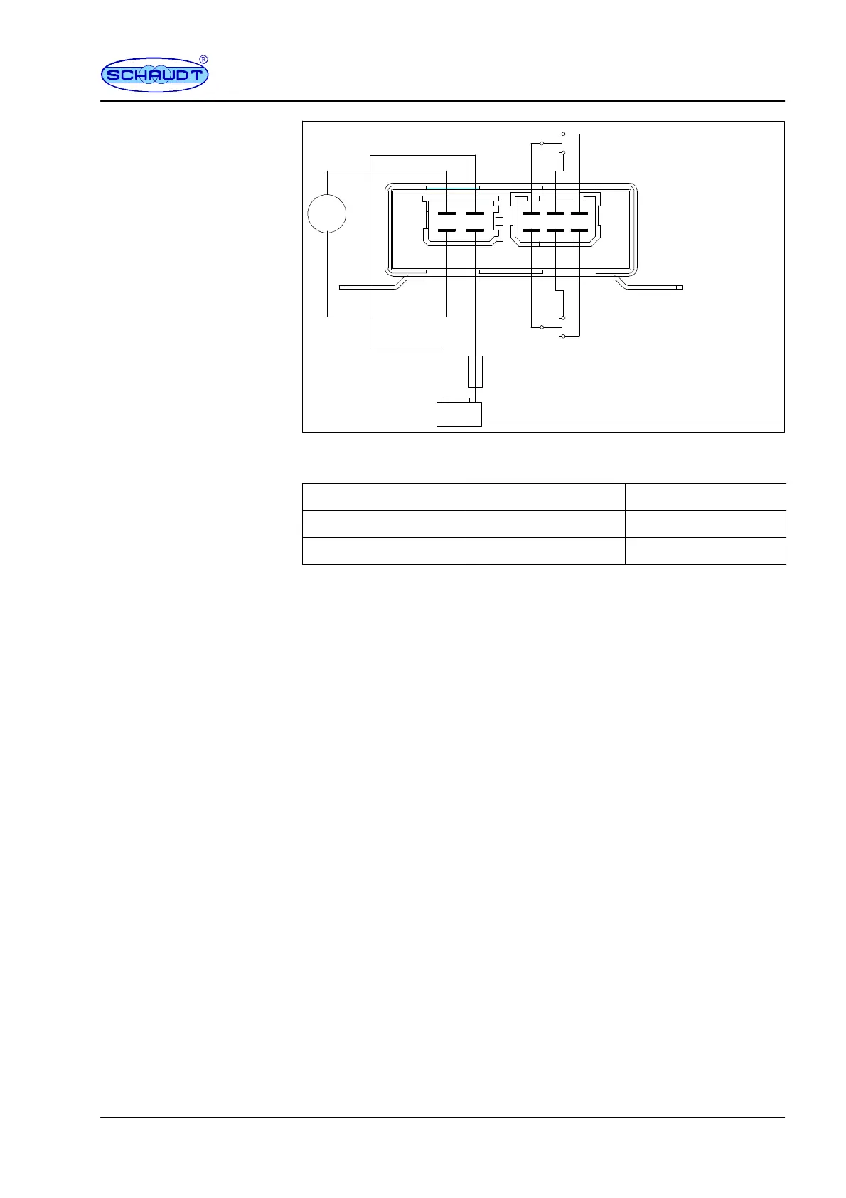
Fig. 2 Block diagram connection EMS 03-4
The polarity of the connections ”motor” is as follows:
Button in position
Connection ST2 - 1 Connection ST2 - 3
Drive in/lock + --
Drive out/open -- +
5 Initial start up
5.1 Testing before initial start up
" Ensure that the battery for the basic vehicle is properly connected.
5.2 Starting up
The step control is plug and play.
6 Technical d ata
6.1 Technical d ata
96 x 130 x 40 (D x W x H in mm), with plug and assembly bracket
180 g
Black plastic, assembly bracket: Steel plate, 1.5mm galvanised
6.2 Electrical d ata
for 12 V DC systems (10 to 14.5 V)
Stand-by current lower than 2,5 mA
EMS 03-4 can be used for step with following currents:
Operating current step: approx. 3 A
Motor lock current step: approx. 11 A
Switch off current EMS 03-4 : 7.5 A ±10 %
If the motor is not switch off within 5 s via the current, it is automatically swit-
ched off by the time control function.
Before starting up
Dimensions
Weight
Housing
Operating voltage
Current consumption
Motor current
 Loading...