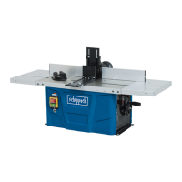
7.0 Séparation des modules (58-59 )
Démonter les boulons de fixations des profils (P) et de la partie rem-
plissage de la dégau (R).
Au remontage : voir chapitre ‘’réglage du guide’’.
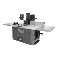
7.1 Retirer uniquement les vis (I) sur les côtés
Les têtes de position (J) permettront de retrouver la position initiale
entre les 2 modules (scie-toupie et dégau-rabot).
P
R
F
GB
D
F
GB
D
F
GB
D
F
GB
D
F
GB
D
58
7.2 Débrancher les connections du moteur, de la commande et du
contacteur dans le boitier électrique Z0 204.
32
7.0 Maschine in Einzelkomponenten zerlegen (58-59)
Längsanschlag Führungsprofil (P) und Hobelmaschine Blende (R)
abmontieren.
Beim wieder Aufbau : siehe Kapitel ‘’Einstellung der Besaümungs-
führung’’.
7.1 Nur die Schrauben (I) auf den Seiten abschrauben
Die Positionsschrauben (J) nie abschrauben : diese Schrauben dienen
als Einstellmarke. Sie sind nützlich um die Ausgangsstellung zwischen
den beiden Maschinen (Abricht-Dickenhobel und Säge-Fräse) wieder
zu finden.
7.2 In dem elektrischen Gehäuse Z0 204 die Anschlüsse des Mo-
tors, der Steuerung und des Kontact Schutzspanhaube trennen.
7.0 Disassembling of the modules (58-59)
Remove the attachment bolts from the profiled sections (P) and
from the packed part of the dressing tool (R).
On reassembly : see the “guide adjustment” chapter.
7.1 Remove only screws (I) from the sides
Locating heads (J) will enable re-adjustment to the original
position between the 2 modules
(shaping saw and dressing plane).
7.2 Unplug the connections of the motor, the command and the
contactor in the electric cabinet Z0 204.
Toute intervention sur l’équipement électrique doit se faire par un professionnel.
Eingriffe auf Stromversorgung ung elektrische Teile dürfen nur Elektrofachleute ausführen.
Only qualied specialists should carry out electrical work.
59
J
I