english 11
maining hazards which are not yet evident may still be
present.
• Remaininghazardscanbeminimizedbyfollowingthe
instructionsin„SafetyPrecautions“,„ProperUse“and
in the entire operating manual.
• Donotforcethemachineunnecessarily:excessivecutt
ing pressure may lead to rapid deterioration of the blade
anda decreasein performance interms ofnish and
cutting precision.
• Avoid accidental starts: do not press the start button
while inserting the plug into the socket.
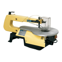
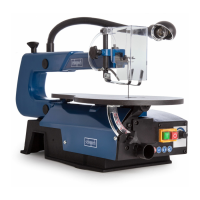
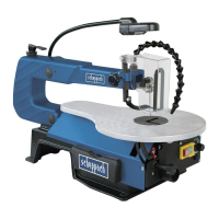
Scroll Saw Design Features, Fig. 1
1 Quick release and tension lever: forquicktensioningand
removalot the saw blade with a handle on the lever.
2 Blade guard: protects your hands from injury.
3 Work piece holder
4 Shavings blower: keeps the workpiece area free from
dust.
5 decotronic: electronical speed switch
deco 402: Speed switch
6 On/Off switch
7 Angle scale: you can read the angle position of the table
with this scale.
Installation
Setting the saw bench, Fig. 2
Setting the angle scale
• Releasethestarbuttonandbringthesawbench(2)toa
rightangle(3)inrelationtothesawblade.
• Use a 90° angle tc measure the right angle between
thebladeandthebench.Thesawbladebe90°tothe
angle.
• Closethestarbuttonagainwhenthedistancebetween
thebladeandthe90°angleisataminimum.Thebench
shouldthenbeat90°tothesawblade.
• Releasethe lock screw and bring the indicator tothe
zero position. Fasten the screw. Please note: the angle
scaleisausefulpieceofsupplementaryequipment,but
should not be used for precision work. Use scrap wood
for saw tests, adjust the bench if neces sary.
Note: The bench should not be on the motor block, this can
cause undesireable noise.
Horizontal saw bench and diagonal cuts, Fig. 2+3
• Thesawbenchcanbepositionedintoa450diagonal
position or be left in the horizontal position.
• Youcanreadofftheapproximateslopeanglebyusing
the angle scale located under the work bench. For more
exact adjustment, use scrap wood for some saw tests;
adjust the bench if necessary.
Blade guard assembly, Fig. 4
Install the blade guard to the holder as shown in the dia-
gram. Secure the screws with a nut and washer.
• Liftthesawontotheframeandbaseandpushitonto
the workbench.
• Familiarizeyourselfwiththesawoperatingelementsand
features.
Mounting the saw on a work bench, Fig. 5
• Aworkbenchmadefromsolidwoodisbetierthanone
made of plywood, as interfering vibrations and noise are
more noticeable with plywood.
• Thenecessarytoolsandsmallpartsforassemblingthe
saw on a workbench are not supplied with the saw. How-
ever,useequipmentofatleastthefollowingsize:
1 Saw body
2 Foam rubber base
3 Work bench
4 Flat seal
5 Washer
6 Hexagonal nut
7Locknut
8 Hexagonal bolt
Ouantity Description
4Hexagonalbolts(6mm)1/420xlength
4Flatseal(7mm)9/321.0
4Washers(7mm)9/321.0.
8Hexagonalnuts(6mm)1/420
First of all, drill holes into the seating surface and then
insert the screws.
• Afoamrubberbaseforreductionofnoiseisnotsupplied
with the saw either. However, we expressly recommend
that you use such a base to keep vibration and noise to
a minimum. Ideal size 410 x 320 mm.
Changing the saw blades
Warning: Switch off the saw and remove the mains supply plug
before installing saw b!ades in order to avoid injuries caused
by unintentiona! activation of the saw.
A. Flat saw blades
A.1 Removing the saw blades, Fig. 7
1 First af all, release the tension via the tensianing tap ta
remave the saw blade.
2Undothescrewsetontheupperbladeholder(Fig.8).
3 Undo the lower holder. To do this, use the spanner which
you can feed through the saw blade slot.
4Removethesawbladebypullingitforwards fromthe
holders and by pulling it through the access hole in the
bench(Fig.9).
A.2 lnstalling the saw blade
1Wheninstallingthesawblade,rstofallpullitthrough
the saw blade slot in the work bench.
Note: In order to avoid tearing or lifting of lightweight work-
pieces, the saw blade teeth should always face down towards
the work bench.
2 Guide the saw blade into the lower holder and fasten the
screws(Fig.9).
3 Guide the other end of the blade into upper holder and
fasten the screws. Push the upper arm of the saw slight-
lydownwardsbeforetighteningthescrews(Fig.10).
4 Tension the blade by turning the tensioning tap clock-
wise.Checkthebladetension.Carryonturningclock-
wisetotensionthebladefurther(Fig.11).
Note: It is difficult to open the tensioning tap again if the blade
is too tightly tensioned.
Saw blade with pins
Note: The upper and lower holders should not be tightened
too much when using saw blades which have pins. The gap
between the holding blocks must be slightly wider than the
saw blade. After installation, the blade is held in place by the
tensioning device.
B.1 Removing the saw blade, Fig. 7
1 First of all, release the tension tap.
2 Take the saw blade out from the upper and lower holder.
Push the upper arm of the saw slightly downwards be-
fore tightening the screws.
B.2 Installing the saw blade
1 Guide one end of the saw blade through the borehole in
 Loading...